There are a lot of online repositories to download video game ROM images. Whether it’s from a website or BitTorrent, you end up with a collection of binary files, each file corresponding to the code stored on a cartridge or an arcade machine’s internal chips, which you can then load into a console or arcade emulator. All of these ROM depots come with a disclaimer of gray-area legality. They effectively say “you’re not allowed to download and use this ROM image unless you already own the game in question.” The law allows you to make personal backups of media you own, so the bootleg download counts toward your backup copy…? I guess…? I am not a lawyer.
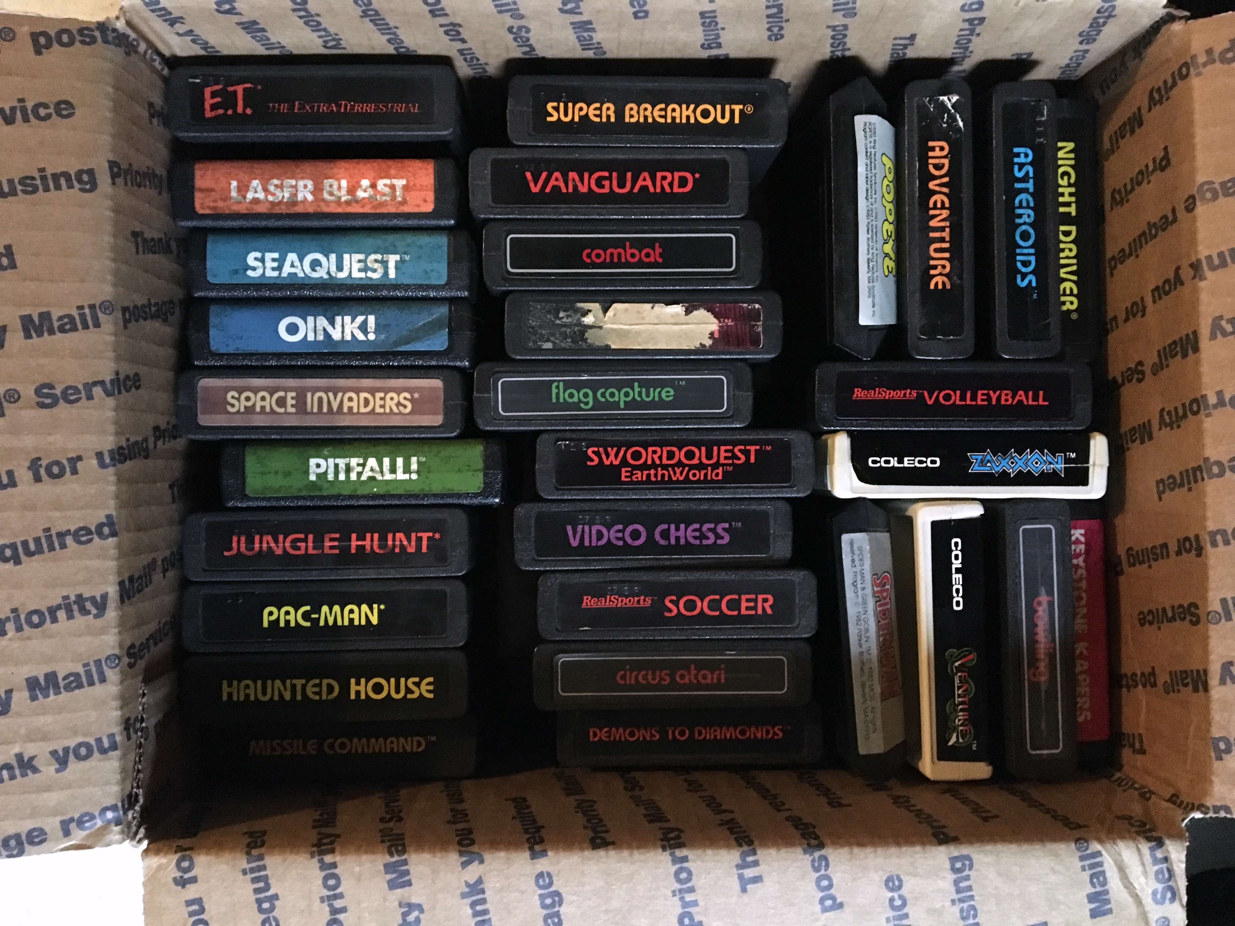
Over Christmas, my mom found a box of old Atari cartridges while cleaning out the garage and asked if I wanted them. I was happy to take them, with the idea of setting up an classic Atari system, but a secondary idea began to germinate. I know the Atari is a simple system, with simple ROM cartridges.
I wondered how easy it might be to extract the ROM images myself — a bit-for-bit archival backup without messing around with downloading gray-market cartridge images. It turned out, despite a few hardships and limitations, to be much easier than I thought.
The Concept
You can find the Atari cartridge pinouts online. It’s a simple scheme with 13 address lines and 8 data lines. All logic levels are 5V, which happens to pair well with an Arduino. There are almost enough pins on a basic Arduino to reach all addresses and read back data, without having any extra support chips for logic level conversion. I also found the correct Atari cartridge edge connector from Digikey. It looked like the build would be as simple as plopping the connector onto a breadboard and wiring it directly to an Arduino, with zero support components. I set about to breadboard a proof-of-concept design.
The Reality
I ran into several problems at start. Feel free to skim or skip this section if you don’t care about the messy technical details.
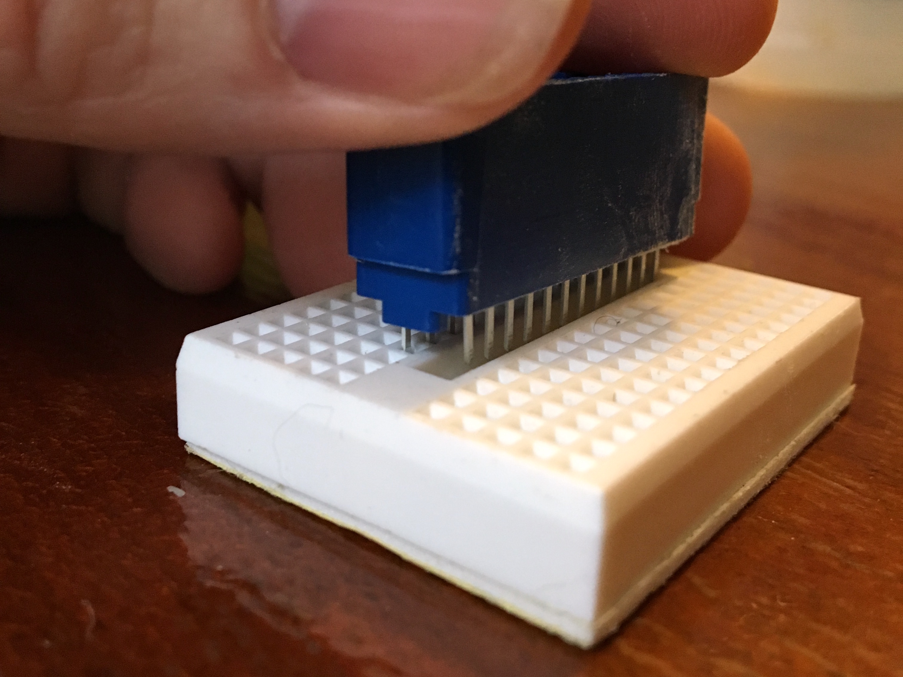
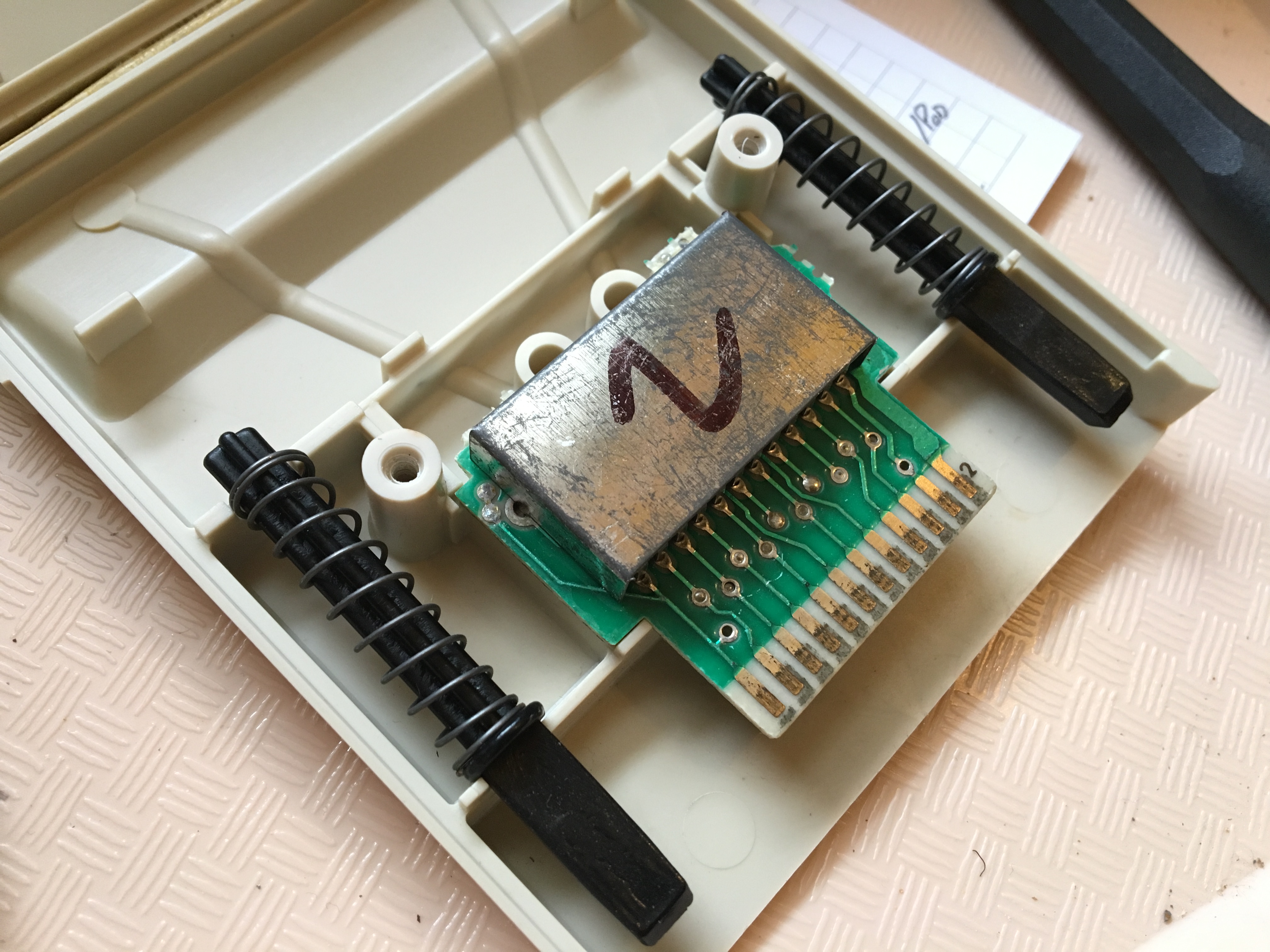
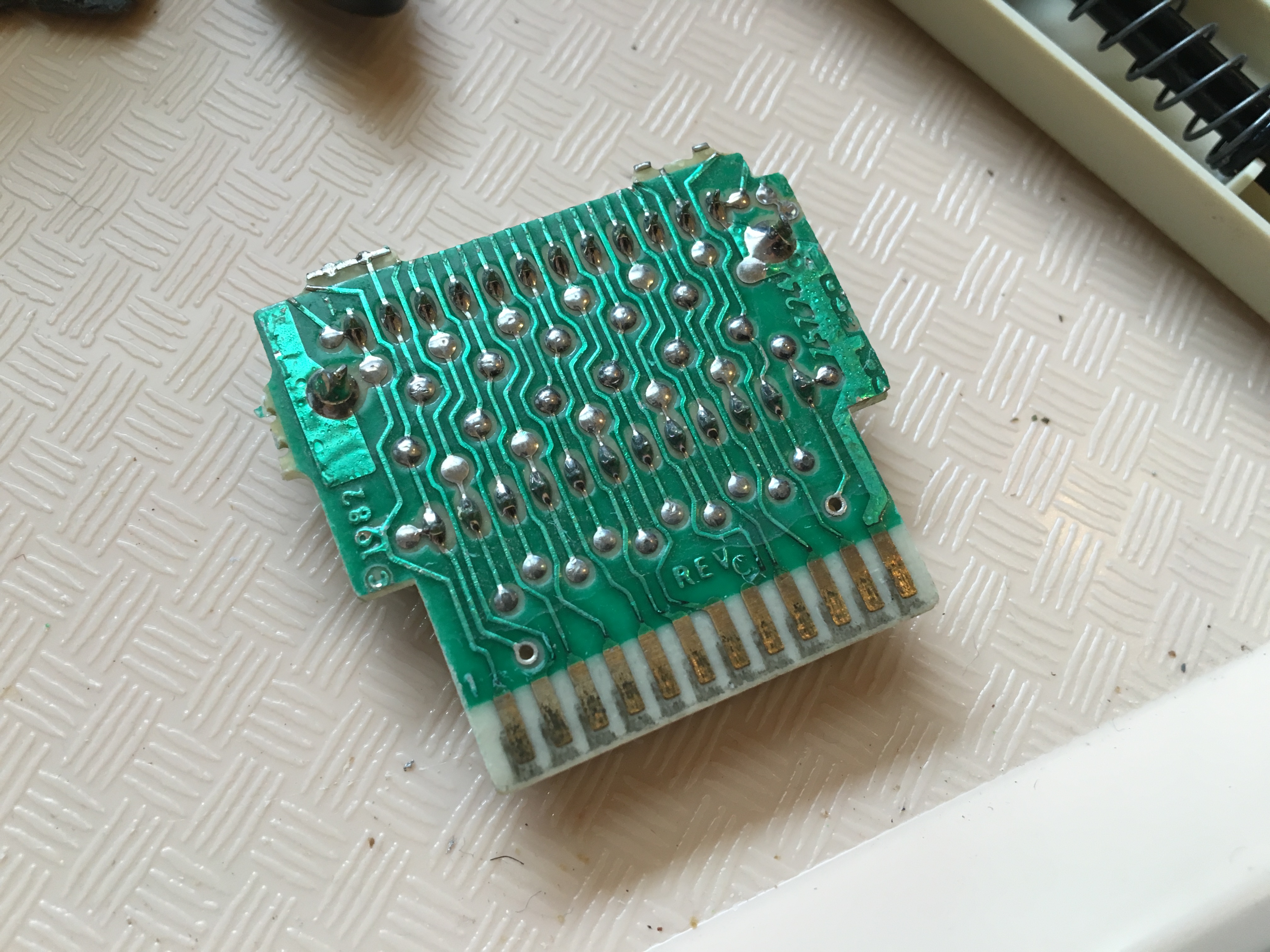
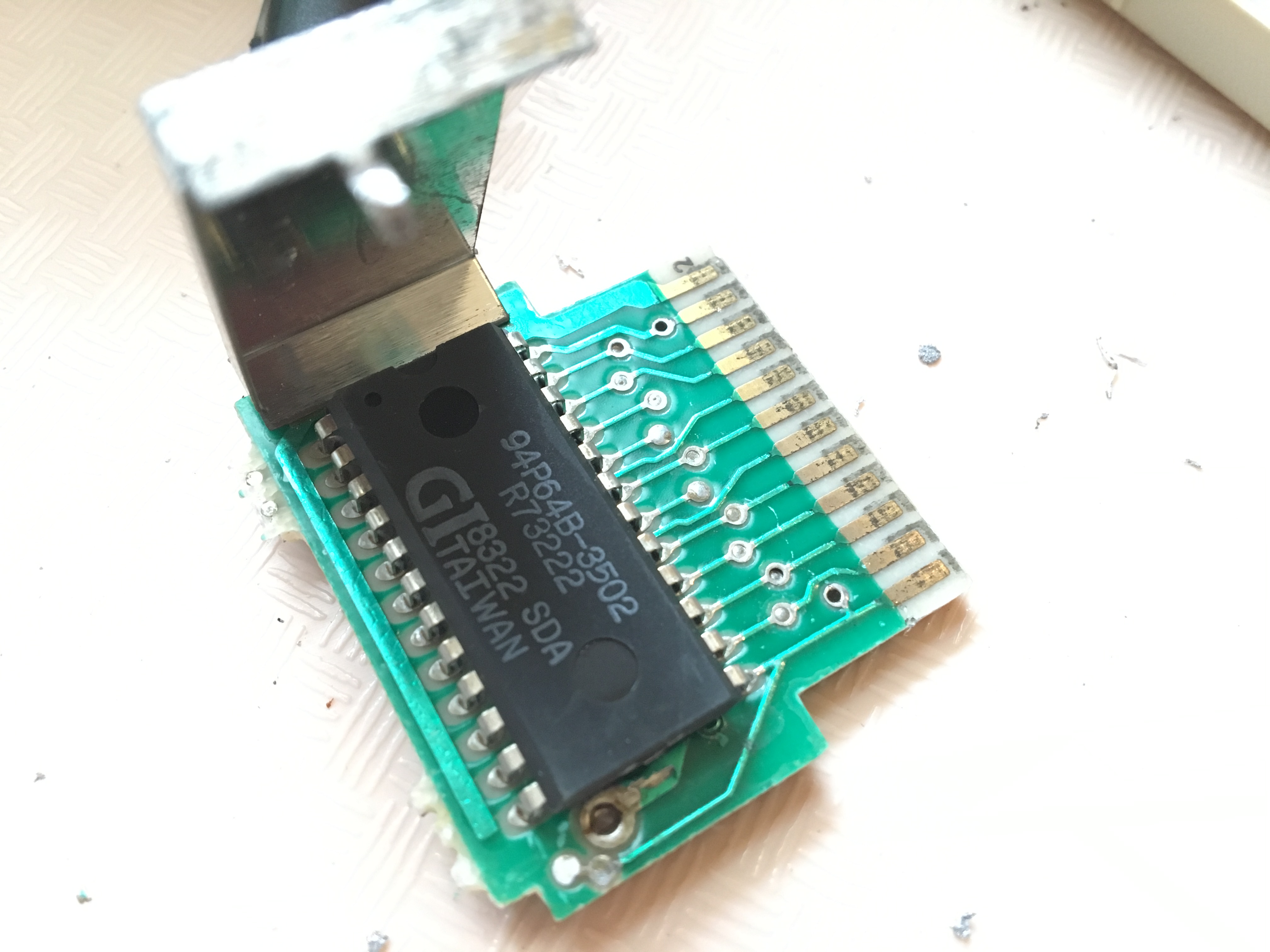
First and foremost, the legs on the cartridge socket are too narrow to span the standard-size gap in most breadboards. The gap is designed for DIP-style chips: one row of pins, two rows of space, and the other row of pins. This socket only has one row of space, so falls short of spanning the gap in the breadboard. I figured I could solder it into a protoboard with only rings (not the stripes you get from a breadboard), then do some ugly soldering to connect the ring holding a socket connector leg to a neighboring ring holding a folded-over a hookup wire end.
When working this out, I hit the second problem. If you push the cartridge socket flush to the board — as you’re supposed to with this style of through-hole package — the socket itself isn’t tall enough to reach the card edge of the cartridge. To give it enough clearance, I had to lift the socket on its legs as tall as I could get it. This meant putting masking tape on the back and putting the socket through the holes to rest on the tape, but not push it through the tape. Normally you solder the legs on the opposite side of a through-hole component, but I had to break out a small tip and solder the leg to the ring on the same side: between the connector and the protoboard.
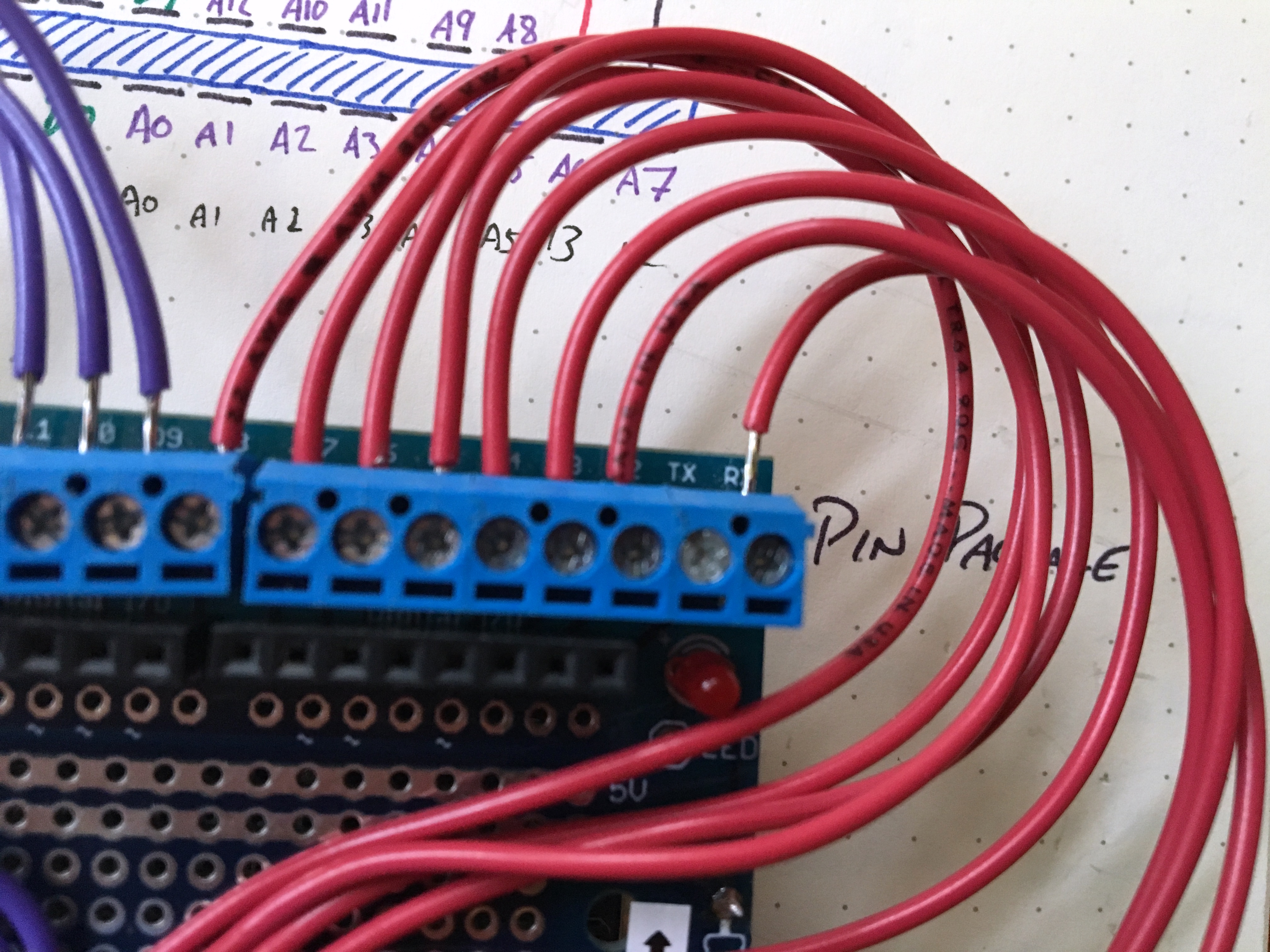
Finally, I didn’t have as many free Arduino pins as I thought. When penciling the initial wiring sketches, I forgot that the Arduino’s D1 pin doubles as the serial port transmit line: the line I’d need to send the content of the ROM back to a desktop or laptop. If I wanted to make images of the larger cartridges then I would have to, for now, manually bank-switch the highest two address lines, extract multiple images, and manually concatenate them together. I don’t have any sort of I2C GPIO extender on hand, and this was all built with junkdrawer parts, so future revisions should migrate some of those address lines off-chip.
A corollary to this is that I was overloading the RX line by using it to also pull data from the cartridge. This means I’m unable to flash new code to the Arduino if a cartridge is plugged in.
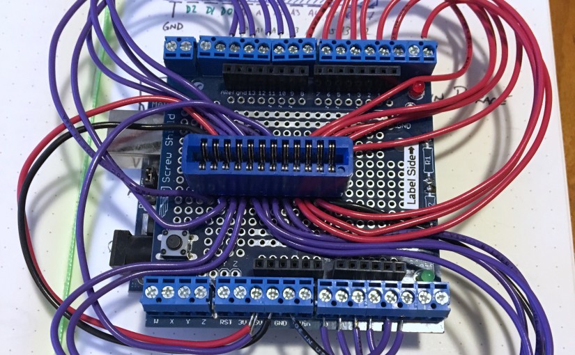
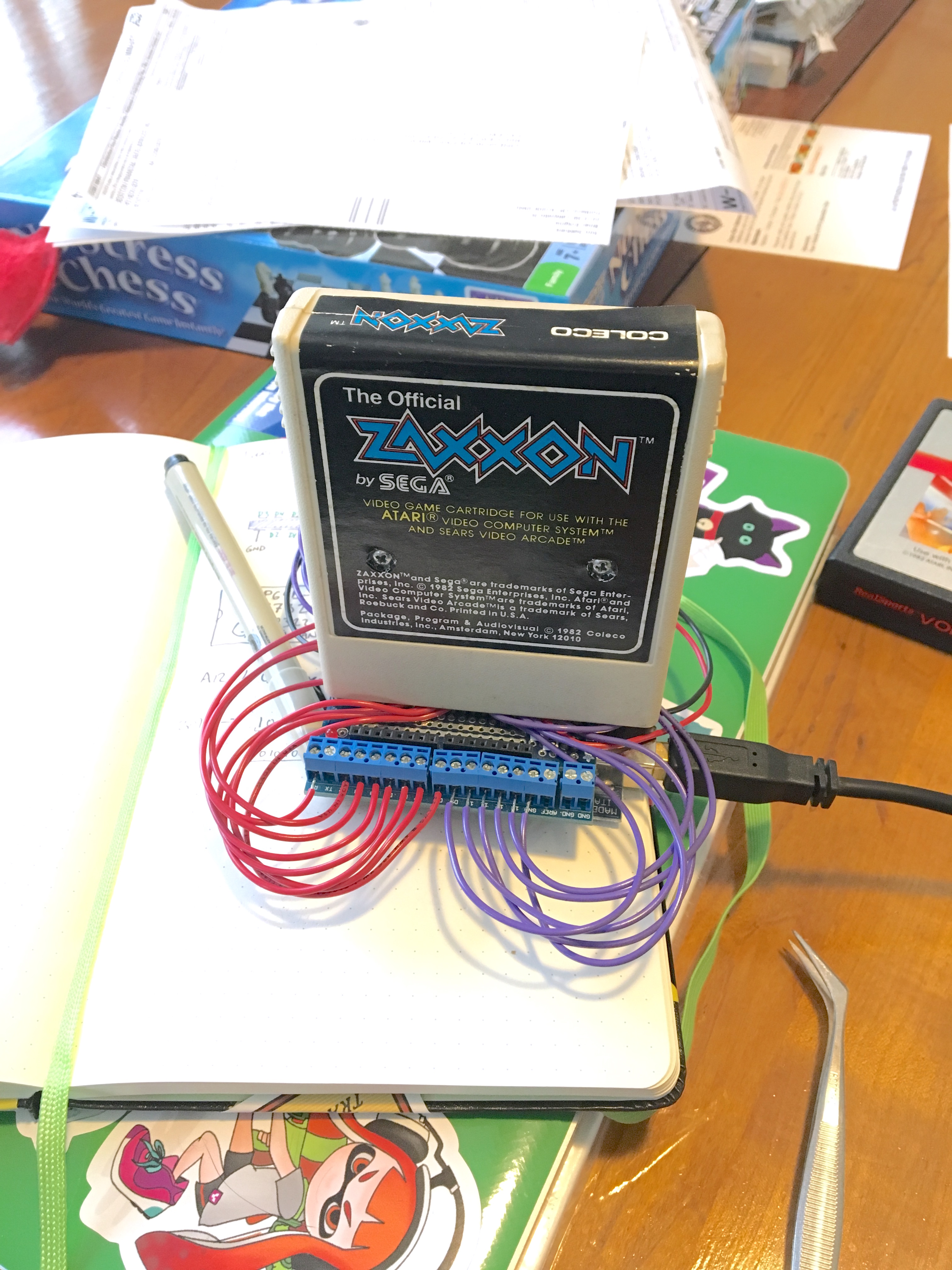
The Hardware

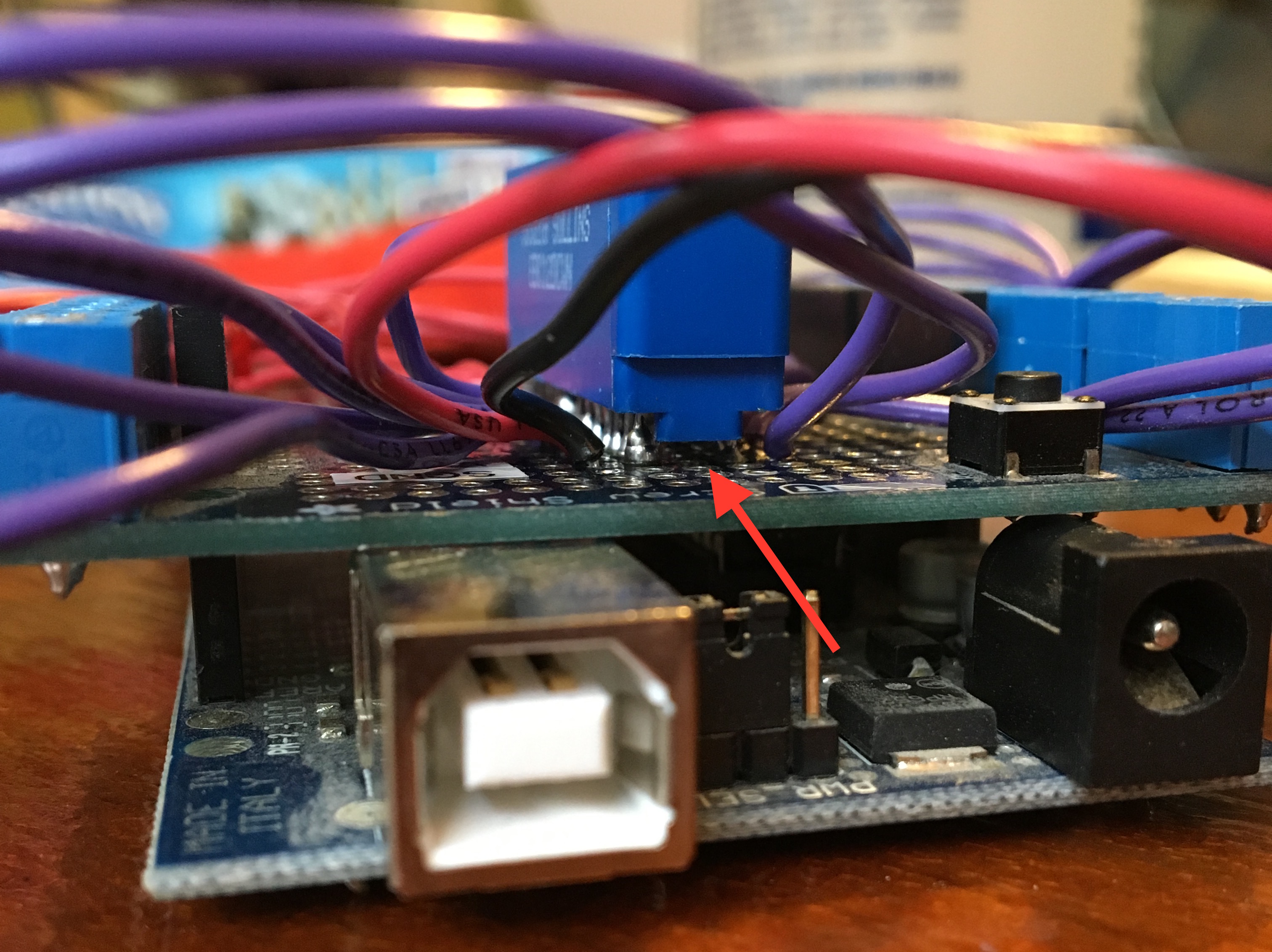
The hardware turned out pretty well, considering this was a quick project that was supposed to be a breadboard exercise and expanded in scope (without revisiting initial assumptions and designs) as it hit the more permanent hardware configuration I needed to get around breadboard and connector difficulties.
The Arduino Software
Given that I only have to directly set and read address and data pins while walking memory, the Arduino software is surprisingly compact. It takes advantage of the built-in serial library to send ROM content back to the laptop/desktop computer. The response is an ASCII hex dump of the current 2K bank the hard-coded high address lines map to. It looks like this:
START
0x0   A9034CD6FAA5822920F00CA5EF2907F0
0x10  0320C1FD20F0FEA9288588A5EBC933D0
0x20  05A9014CD6FAA000C8D9C1FEB0FAB9C0
...
0x3E0 DDB0F4E69CA59C20D5FD859C2085F985
0x3F0 E2A59C18690C858DA58B186934858FA5
END
(This ROM dump is the Zaxxon cartridge, for what it’s worth.)
The Reassembly Software
The desktop Ruby script to validate the hex dump and translate it into a binary file is similarly short. It looks for the START/END tags, verifies that each line contains 16 bytes, each address increments by 16, and writes those bytes to a binary file.
Usage
Once you have uploaded the reader code into the Arduino and have wired up the two high address lines to hit the bank you’re after, you simply reset the Arduino and plug in a cartridge. The cartridge reader software counts down from 10 seconds, then pulls content from the ROM and outputs it to the serial port. You can use the built in Arduino IDE serial monitor and copy/paste the ROM dump to a text file, or you can open up a serial terminal emulator like Minicom and log to a capture file. The reassembly Ruby script then translates this into a binary image. If you need to combine multiple banks, a simply shell command like `cat dump1.bin dump2.bin > fulldump.bin` will combine the images.
Next Steps
This project started out as an academic “what if” to see how easily I could extract an Atari game image. I made it in an afternoon using parts I have on hand. (I try to keep a spare Arduino and protoboard shield on hand for these sorts of projects.) Were I to revise the design, I would take a few things into consideration:
- I need to stock a few spare I2C GPIO extender chips in my parts bin. Manual bank-switching is a pain. I would then revise the design to migrate two of the high address lines (plus the missing ones) to the GPIO extender chip, freeing pins for I2C. I might even remap one more address line to free up the serial RX pin.
- I need to solve the problem of the card-edge connector’s reach. This means either locating a taller component or designing some sort of riser.
- I have a 3D printer and know how to use it! Although a few cartridges have exposed card edge connections, most need a pin to push into a latch release before exposing the card edge. It’s easy enough to do this manually with a plastic spudger tool, but it would be mega-cool to include 3D printed release pins in the design.
- It might also be fun to see if I can detect when a cartridge is inserted or removed. The homebrew cartridge documentation implies that ground and shield-ground are usually (always?) tied together. I might see if I can use shield-ground for detection.
- Tie it to an emulator? Instead of dumping the ROM image to disk, why not feed it to an emulator? This would give you an emulator that accepts physical cartridges instead of downloaded images.
Obviously there are plenty of places where you could take the project from here, but I’d call this a successful proof-of-concept. The full code and technical documentation live in my Arduino/Atarireader GitHub project.
I’m interested in doing this project to read Atari cartridges with an Arduino, but I want to use an Arduino Due since it has more IO pins needed by the cartridge. However, the Due is 3.3v logic. I know that I need to use logic level converter/voltage divider to set up the voltage to 5v. I’m new at this, so I don’t know if I need to raise each of the pins leaving the Due to 5v, or if I only need to raise the cartridge’s 5v pin to 5v. I hope you can answer soon. Thanks in advance!
If your board can only drive 3.3 on the pins, you’ll need something like a logic level converter, as you suggested, on the address and data lines. It’ll translate the 3.3v coming out of the address lines to 5v on the cartridge and, similarly, translate the 5v coming back from the cartridge data lines, to 3.3v on the Arduino pins. The one I like (https://www.sparkfun.com/products/12009) is a simpe bi-directional one that’s easy to work with, but is maybe overkill for this case (you just need output on the address and input on the data lines, not full symmetry across all the lines).
Thanks for the quick response. But now, to make things more simple and cost efficient, I think I’m going to use an Arduino Mega since it has 5v logic and the same pin layout as the Due. My intention was to send the binary image to a Raspberry Pi 3 (which uses 3.3 logic) over serial. I’ll use a logic level converter for that instead of the cartridge.
Sir. Brian. Firstly, I’m very surprised. Because I search the entire internet in search of a project similar to yours and the only thing I found before finding your project was one for Arduino mega, but this one did not meet my expectations as your project.
And what I’m surprised, is why I have not found this project before? I’ll share it in a facebook group that I’m part of here in Brazil. And I will try to share in other groups as well.
Sir. Brian, I want to use your project to try to make the consoles read the rom from sd card module adaptor. I want to do this with the Sega Master System. My problem is that I studied programming and electronics at the basic technician level, I’m not a college graduated . I have a lot of trouble studying assembly language and other subjects in this area alone. The courses in my country are very expensive.
I plan to use an Arduino Uno with shift registers to increase the number of Arduino ports. Since my goal is to make the videogame read the roms from sd card adaptor, will I need to modify the Address and Date lines in your sketche?
Thank you in advance for sharing such a wonderful project.
Best Regards.
Unfortunately, I do not know enough about Sega Master System cartridges or your SD Card cartridge to be able to answer your question.
Thanks for answering me. As I said before, I have notions on a technician level. I know that, just like Atari, video games like NES, Sega Master System, Sega Genesis (Mega Drive) and SNES, also work with EPROM 27c series. I think the data pins from 0 to 7, transmit the bits with the game informations to the main processor. I begin to confuse myself with “how work the address pins”. I already tried to learn reading about memory mapping, but without showing me how it is in practice, I can’t learn. There is a website called next-hack.com, which teaches how to transmit a video from the SD card to a mini LCD display module through the Arduino. I am trying, with many difficulties, to use this concept to try to develop my project. With the help of your project, I’ll try to start some tests. Once again, I thank you.
Best Wishes.
For anybody still interested in this, you might find this hackaday project of interest:
https://hackaday.io/project/113217/logs
It uses a STM32duino “bluepill” instead of regular Arduino, though. Still, he sandwiched the STM32duino (an ARM based thing) together with a pi zero and these are then connected to a cartridge edge connector (he has some 3d printer files for the cartridge holder too). I was hoping something equivalent existed for regular atmega Arduinos since I don’t have the skills to port the C over. I haven’t tried this hackaday project. It looks really cool. And I’m just assuming it works.
Or to put it another way: thank you for this article.