This is one in a series of Halloween electronics posts. Read the full series:
Last Halloween I built some animated light-up steampunk/mad-scientist goggles. I did this at the same time I did the creepy motion-activated eyes and the ambient lighting with surprise thunder and lightning. Because I was building and refining up until the last minute, I never got around to showing off and documenting the project. This post, a year later, will try to fix that.
I have seen similar projects posted before, but they always had full covers over the lenses and came with warning about not wearing them over your face. Light-leakage and the strobe of the LEDs can lead to headaches. Knowing that I’d only have a narrow field of view anyway (like most masks), I wanted a design that allows for wearing them over the eyes for extended periods of time without the light-leak and headaches. Between laser cutting, 3D printing, and liberal amounts of Sugru, I think I worked it out.
- Goggles I found at an army surplus store decades ago.
- A pair of Adafruit NeoPixel LED rings
- Adafruit Trinket
- Battery pack
- Assorted wire, solder, and miscellaneous materials
My additions included:
- Laser cut rings (54mm outside diameter, 31.75mm inside)
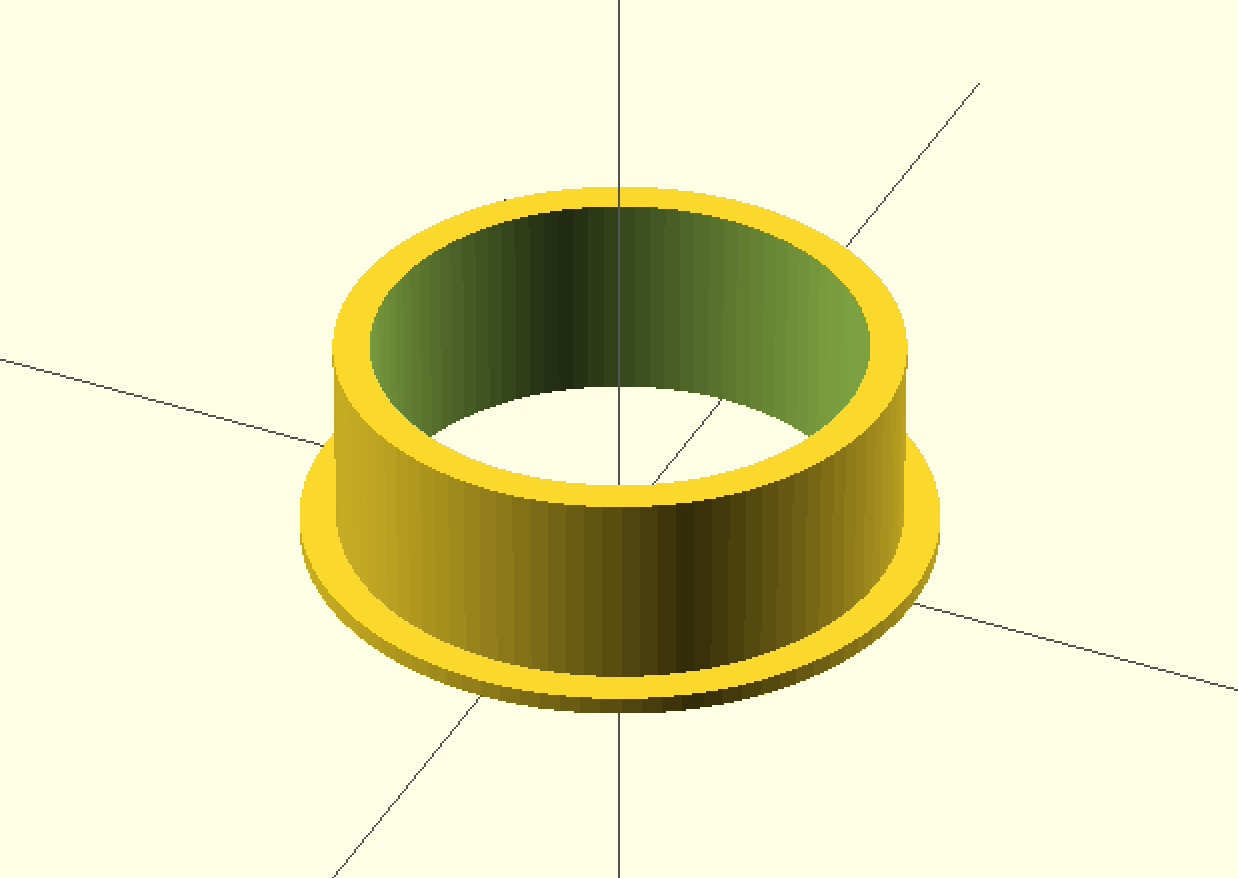
- 3D printed “blinder” tubes (31.75mm outside diameter, 12mm tall)
- A small pushbutton to change animation modes
- A ton of electrical tape (later, I switch to Sugru) to seal around the edges
The whole project is a riff on the Adafruit Kaleidoscope Eyes project, with some of my own hardware and software customizations. Unfortunately, I do not have many pictures of the steps during the build process. It was tedious and detail-oriented. It was mainly cutting and routing wire and soldering things in-place, as opposed to building separately and cramming it all into the goggles afterward. The code lives in the GitHub project as well as assorted other build files (laser cutter paths, 3D models).
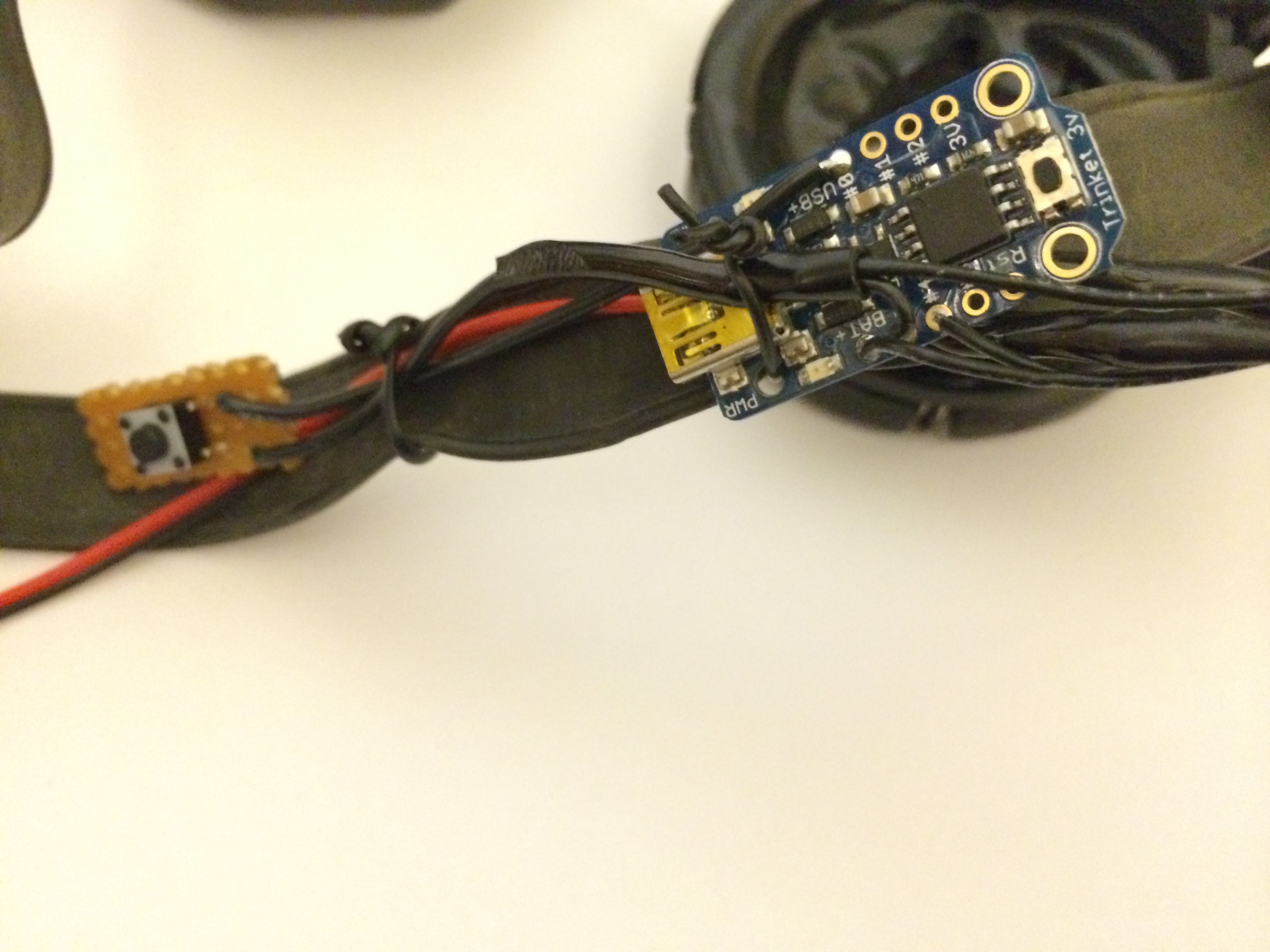
Instead of cramming the Trinket inside the goggles, which would obscure vision, I attached it to the outside strap. This has several added benefits: it’s easier to access for programming and it gives it that extra sci-fi touch. I also added a small button on a perf board to the strap. This is used to switch animation modes.
The goggles are great. They are comfortable and high quality. The thick glass lenses are retained by a metal ring and spring clips, making them easy to pop out, measure, and replace. It was easy to find acrylic of a similar thickness. I laser cut some rings — a 54mm outside diameter to match the lenses and a 31.75mm inside diameter to match the inside diameter of the neopixel rings.
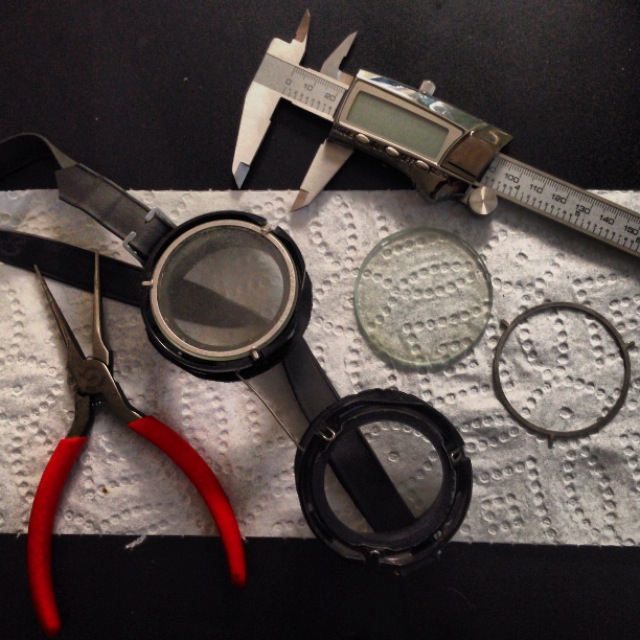
With the acrylic in place and the NewPixel rings crammed in as far as they could go, I measured the distance I’d need for the “blinder” tubes. I’d need a light-proof channel that allows me to peer through the center of the NeoPixel and acrylic ring. I ended up with plugs that are 12mm tall (including the height of the retaining lip around the acrylic ring. You can find my 3D STL file on Github, which is kind of cool because you can spin it around in your browser. The OpenSCAD source code is there, too.

Between exact measurements and 3D print tolerance, it was a fairly decent friction fit. I used a few drops of hot glue to better bridge the tube-to-NeoPixel junction, just in case. There was still quite a lot of light leakage, though. Because the rubber of the goggles is not perfectly circular, there was some gapping there that light came through. There was also a little bit of gapping between the tube and the NeoPixel ring. Unexpectedly, the circuit board itself had a few via holes that let light through. My first round of sealing, from Halloween last year, was with electrical tape. I cut strips and sealed around the NeoPixel-to-goggle junctions as well as the NeoPixel-to-tube junctions. The vias got covered as a byproduct of all the tape I used. It used what I had on hand and it mostly worked. The tape doesn’t stick all that well to the ABS plastic of the tube, so would occasionally peel back and obscure vision for a bit. I’d have to poke my fingers into the eye holes (ew, gross!) and flatten it out. Since then, I’ve embraced the coolness of Sugru. I ripped out all the tape and plastered the whole thing in Sugru.
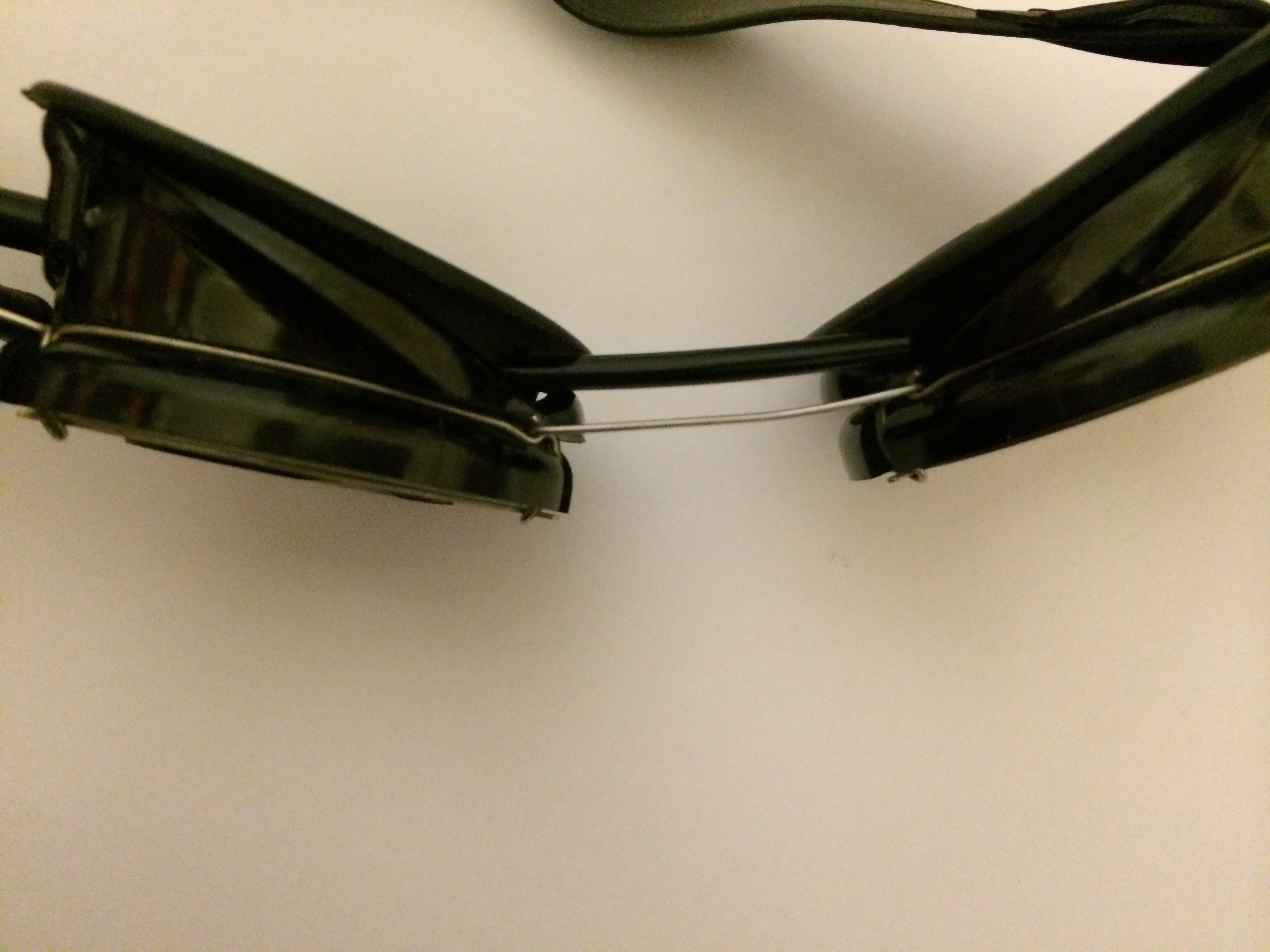
This picture, from after I’d ripped out the tape, shows the difference in light leak between Sugru (left) and nothing at all (right):
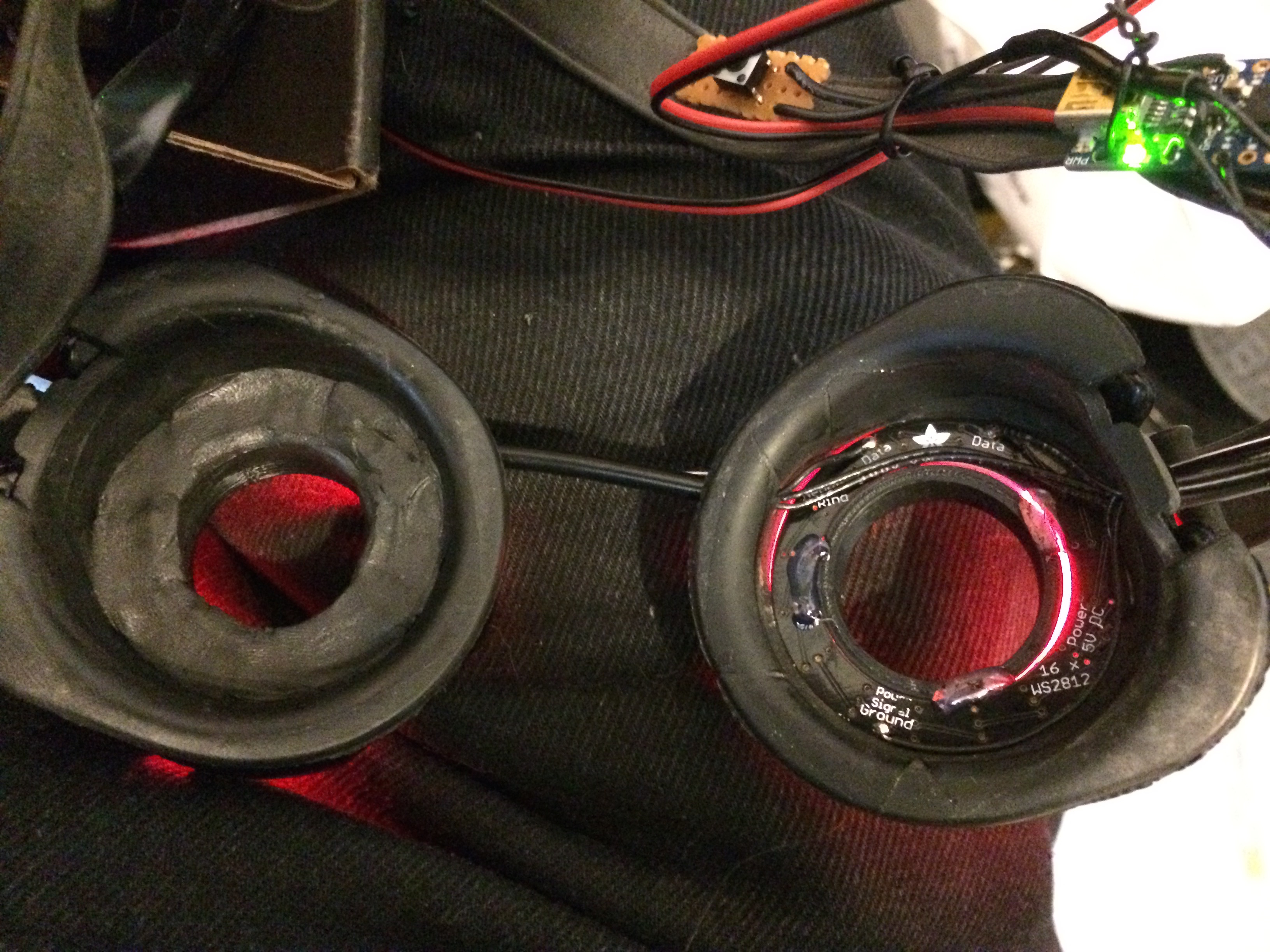
Because there was zero light leakage, every time I switched animation modes, I’d have to hold my other hand in front of my face. The light that bathed my hand and reflected back to my eyes told me what color and motion was actively displayed.
I hope this blog post gives you some insight and inspiration on your own project. It wasn’t intended as a step-by-step how-to, given how custom it is. I’m not even sure I could find equivalent goggles again. My design files and source code are linked in the above article and on GitHub. Feel free to download, edit, and tweak them to suit your own needs.
Thats sooooo cool. Hopefully I will order mine tomorrow and TRY and do the same. We’re trying to build a Robot over here.
Hi Brain ,
Awesome project ! Can you tell me how you wire the button for the mode switch ?
Animation only working if i hold down the button , as soon as i release it , the animations stop.
Please help.
Thanks,
The pin connected to the button has an internal pull-up resistor (as mentioned in the code comment: digitalWrite(BUTTON_PIN, HIGH); // activate pullup). That means that the other end of the button should be connected to ground. During normal operation that pin should read high. When the button is pressed, it should read low.