I basically grew up at Disneyland. As a kid, my family lived about 20 minutes away and we’d get to go twice a year: once on my birthday and once on my sister’s. In my 20s, I had an annual pass and would go on the weekends, or just pop by for an hour after work to have dinner, peoplewatch, and maybe catch a ride or two. My last 10 years have been in the pacific northwest, with only two or three Disneyland trips.
But I had a random thought last year. After playing with the Adafruit Neopixel strips on other projects, I thought I might attach them to some Disneyland mouse ears. I might even have the guts to wear those ears to the park next time I visited.

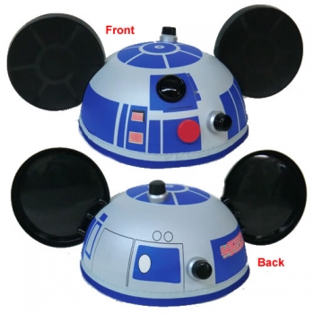
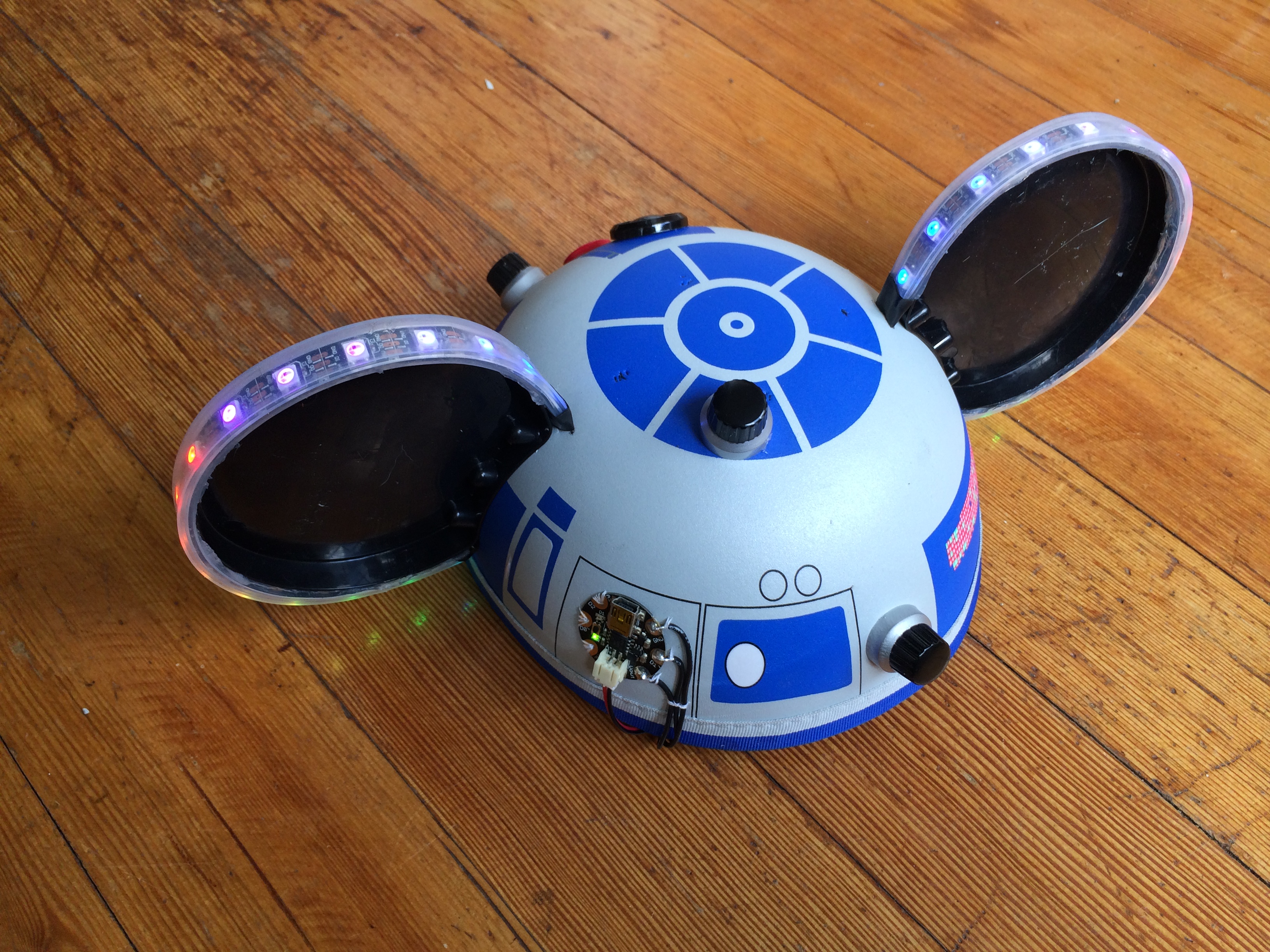
I started with some mouse ears. I wasn’t totally certain that official Disneyland mouse ears would be available outside of the park, but Google brought me to The Mouse Shoppe. Furthermore, I had no idea that there was such ear-hat variety. Given that I was going to drop some electronics into and onto the hat, I opted for R2D2.
The electronics package I came up with is nearly identical to Adafruit’s “Cyberpunk Spikes,” only wrapped around the ears rather than under some silicone spikes. My bill of materials looks a bit like this:
- NeoPixel strip, 60 LEDs per meter, black backing (technically, I needed only 32 LEDs, not the full meter — the rest went, along with a Trinket, to retrofit my nameplate)
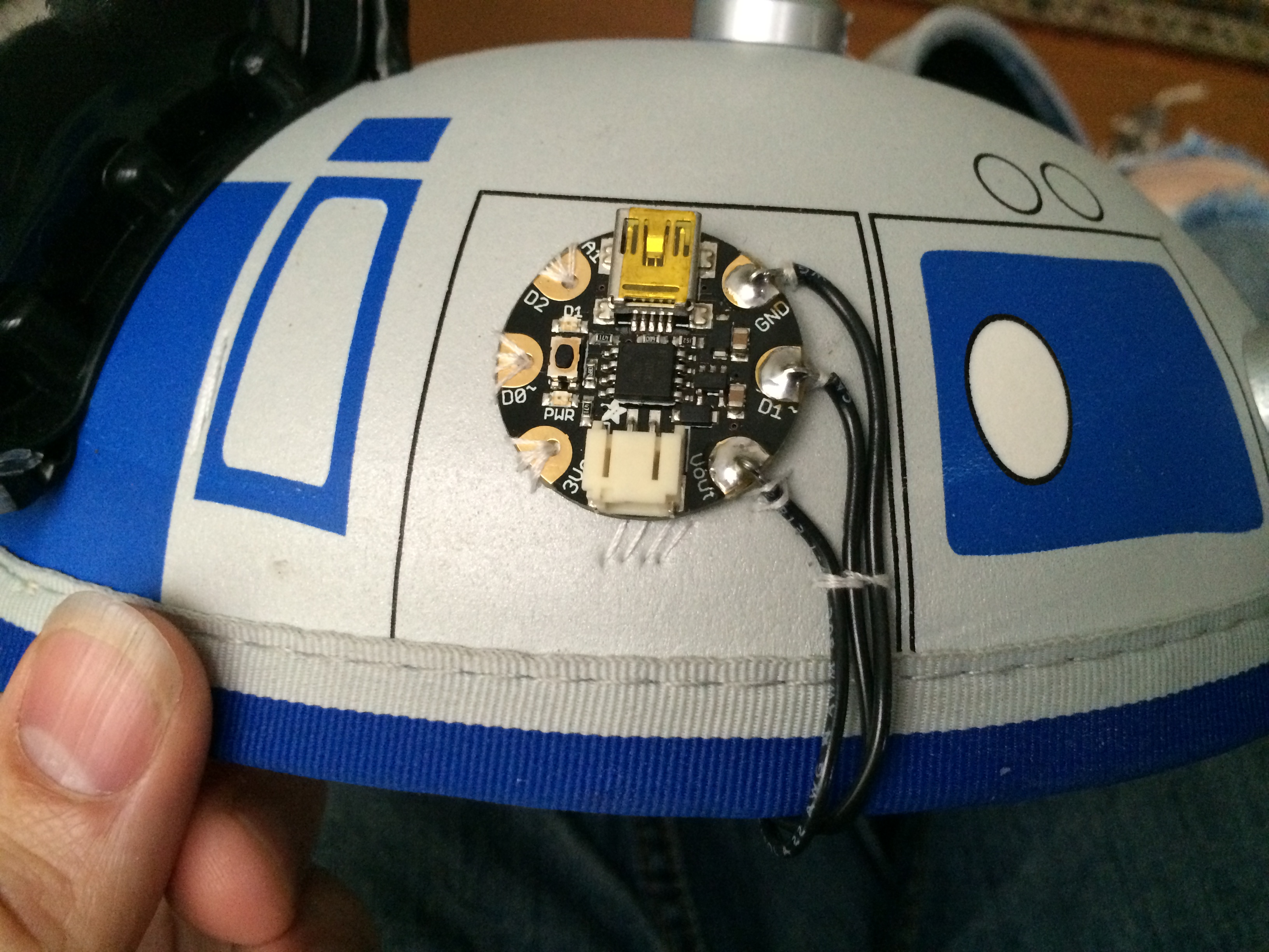
- a Gemma microcontroller for the brains
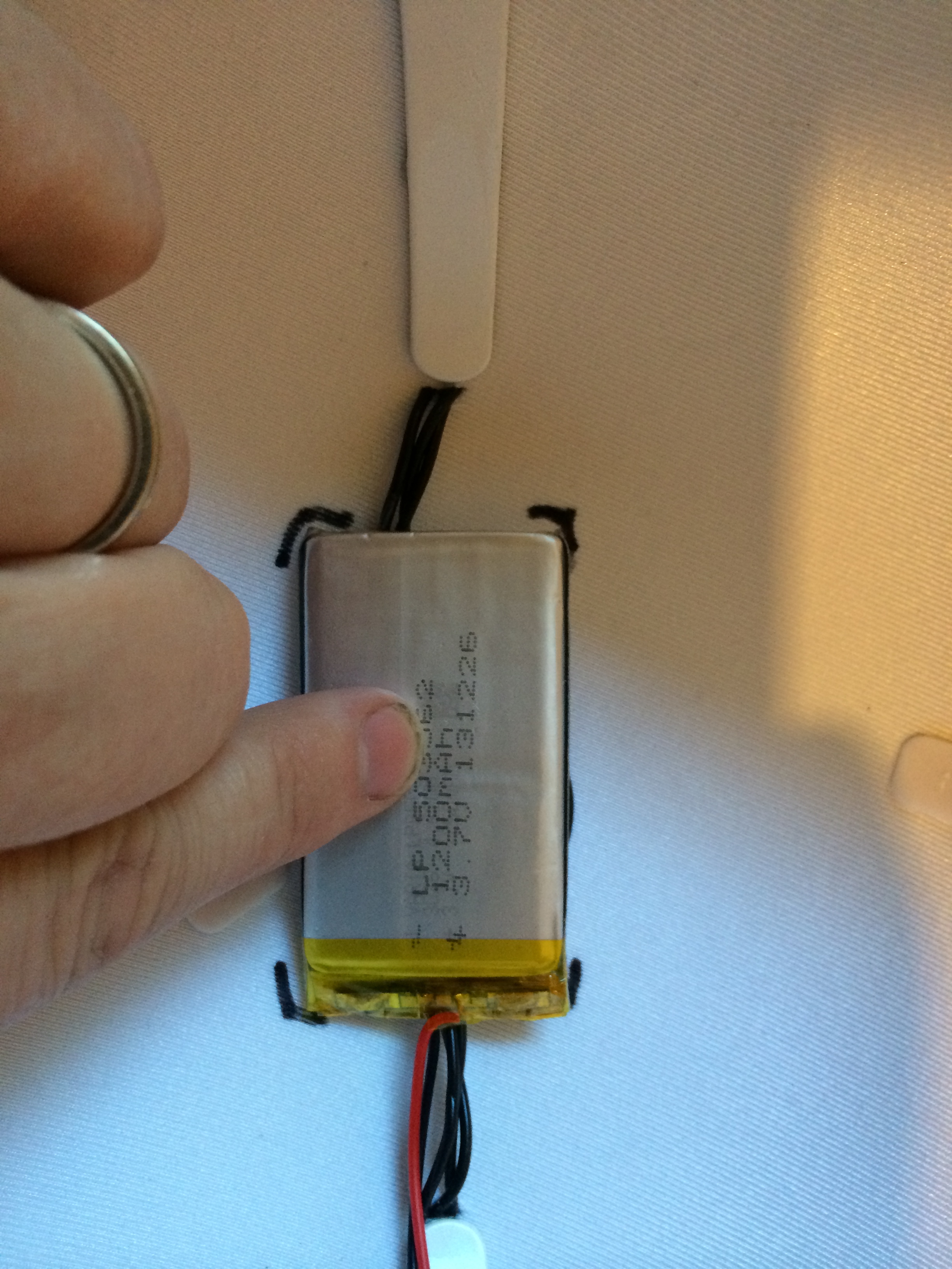
- 3.7v 1200mAh LiPo battery (I bumped up to a larger battery, as compared to the Cyberpunk Spikes project, to give me more time and/or brightness)
- battery extension cable
- USB charger (if you don’t already have one)
The electronics part of the build was fairly easy — the same as the Cuberpunk Spikes project, except with a gap between two LED strips. Getting everything attached to the hat in a way that looks decent was, for me, the challenge.
My plan was this:
- Wire the LEDs through the hat with enough slack wire to make them workable.
- Using temporary solder joints, verify the LED’s wiring against the (unmounted) microcontroller and battery. Unsolder the temporary joints.
- Use small zipties to take in the slack between the LED strips.
- Create a slip-out battery harness using elastic.
- Trim and solder the LED wires to the microcontroller.
- Sew in the microcontroller.
- Glue down the LEDs.
- Sew down any other assorted loose wires.
The ear hat is made of a strange sort of rubberized fabric. Using a hobby knife, I made incisions, enough for three wires (power, ground, data) to fit through. A strip of 16 LEDs fit perfectly around the circumference of an ear so I soldered leads to either end. I didn’t want them too short, as that would mean a lot of rework, and figured I could easily trim them later, so they were longer than necessary.
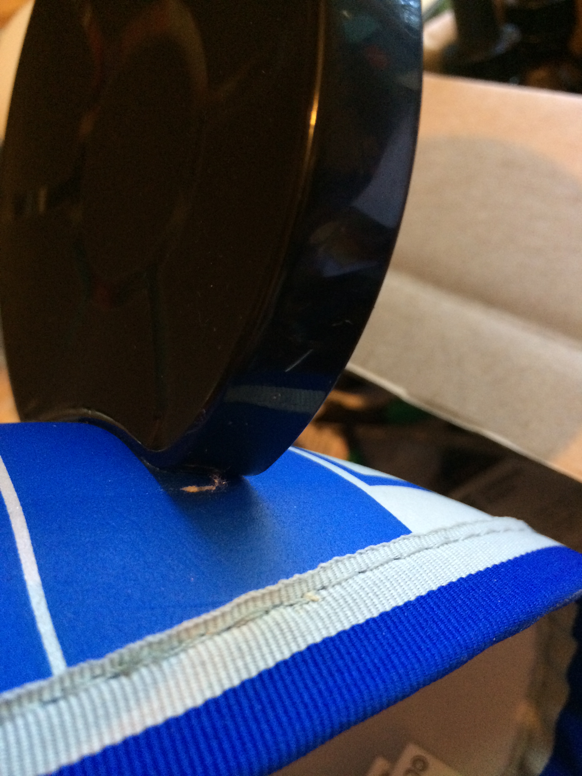
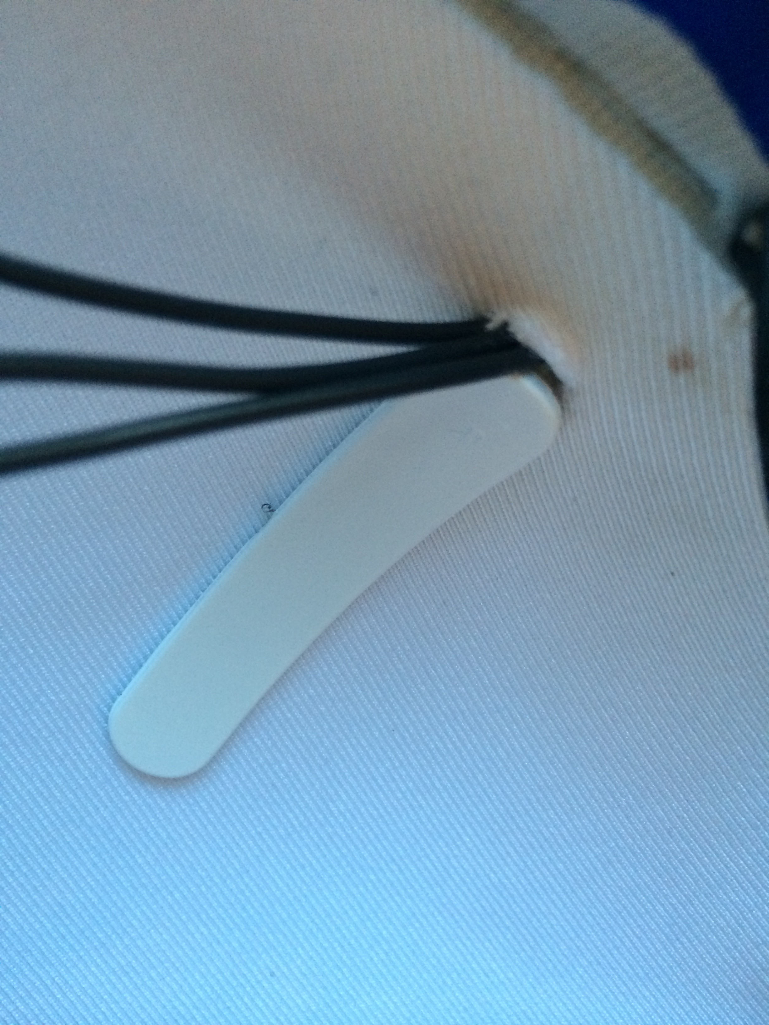
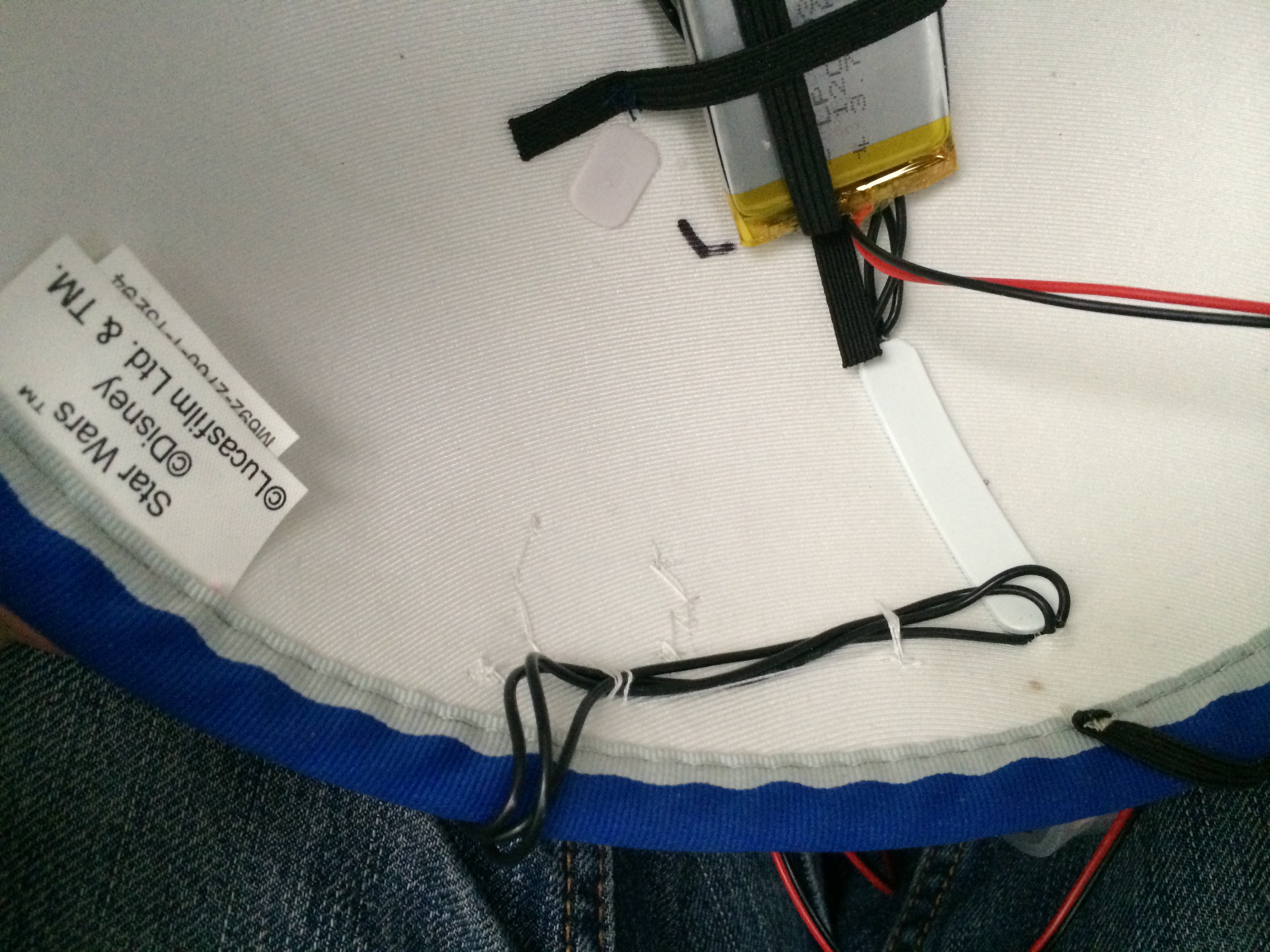
Label the wires! This is important. I used black wire and wrapped the ends of the LED strips in electrical tape to better conceal and protect the solder joints. Without labels, it is easy to mix up your lines.
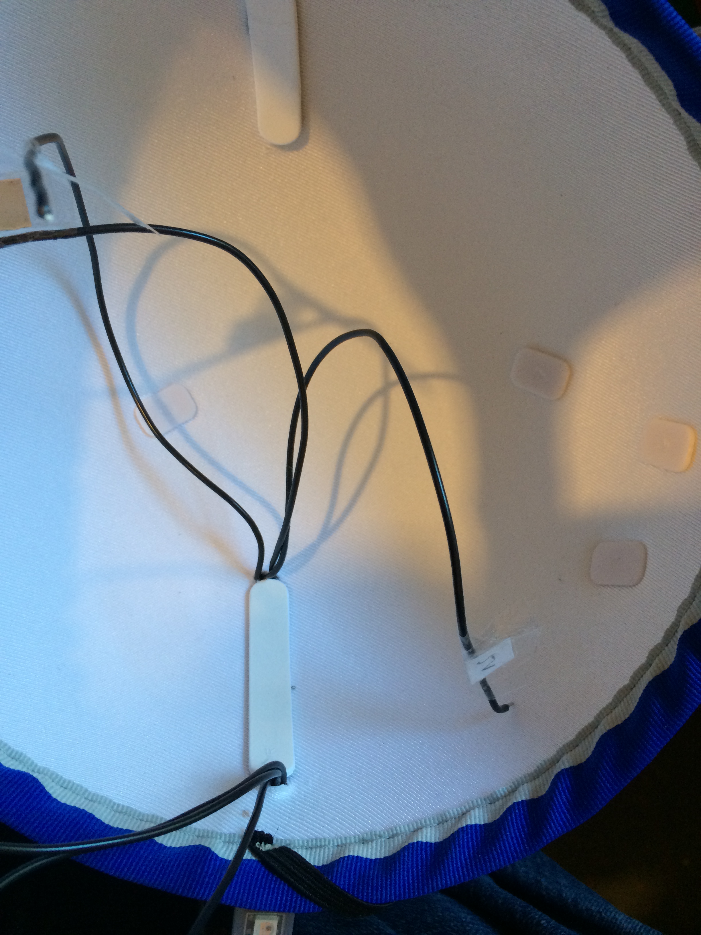
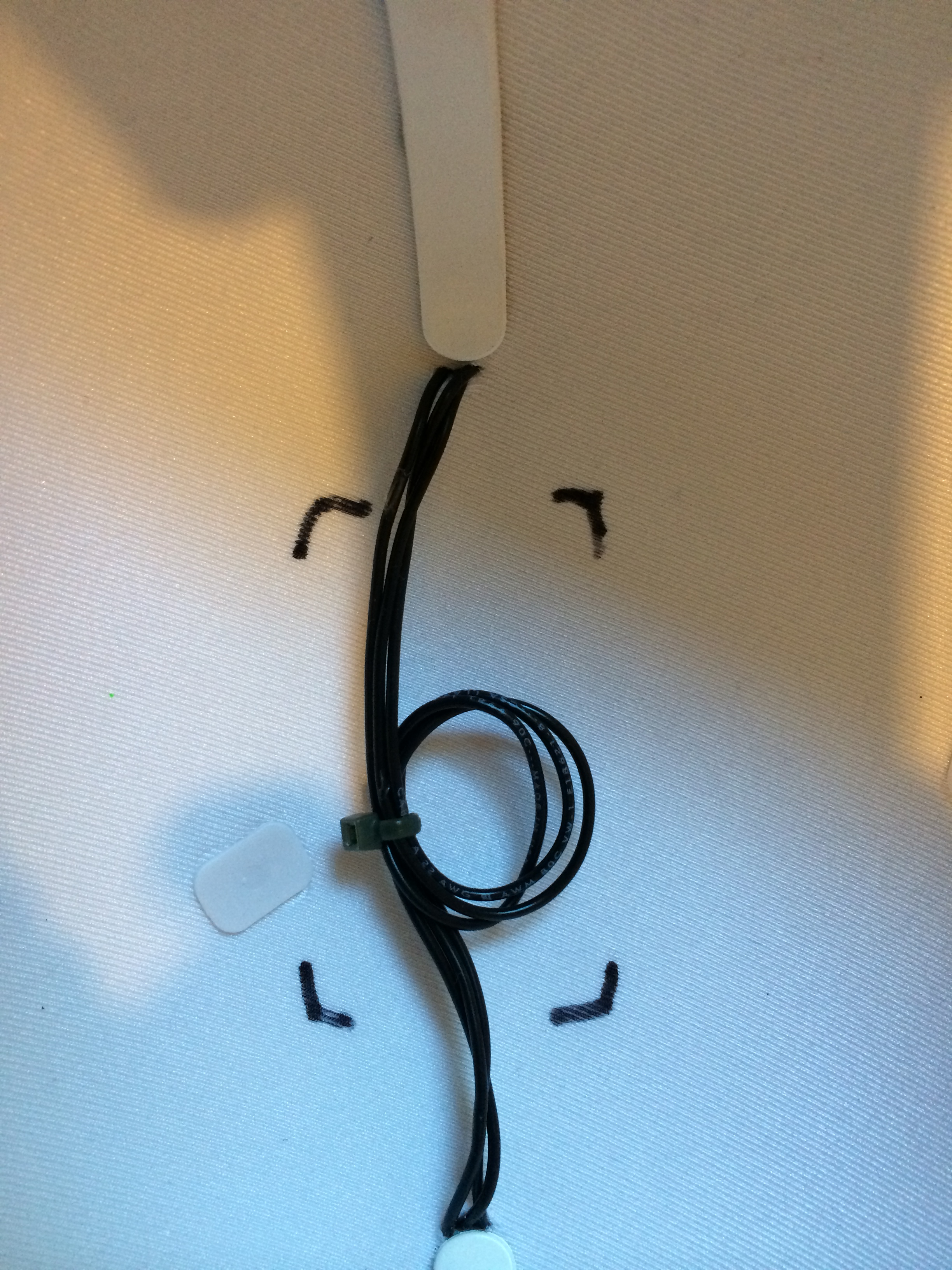
Pass the nice long wires through an incision up near the next ear and carefully wire them to the next strip of 16 LEDs. Once the two sets of LEDs were wired through the incisions, soldered in series, passed my initial testing (but weren’t yet glued down), I pulled in some of the slack between the two strips and bundled it with a ziptie.
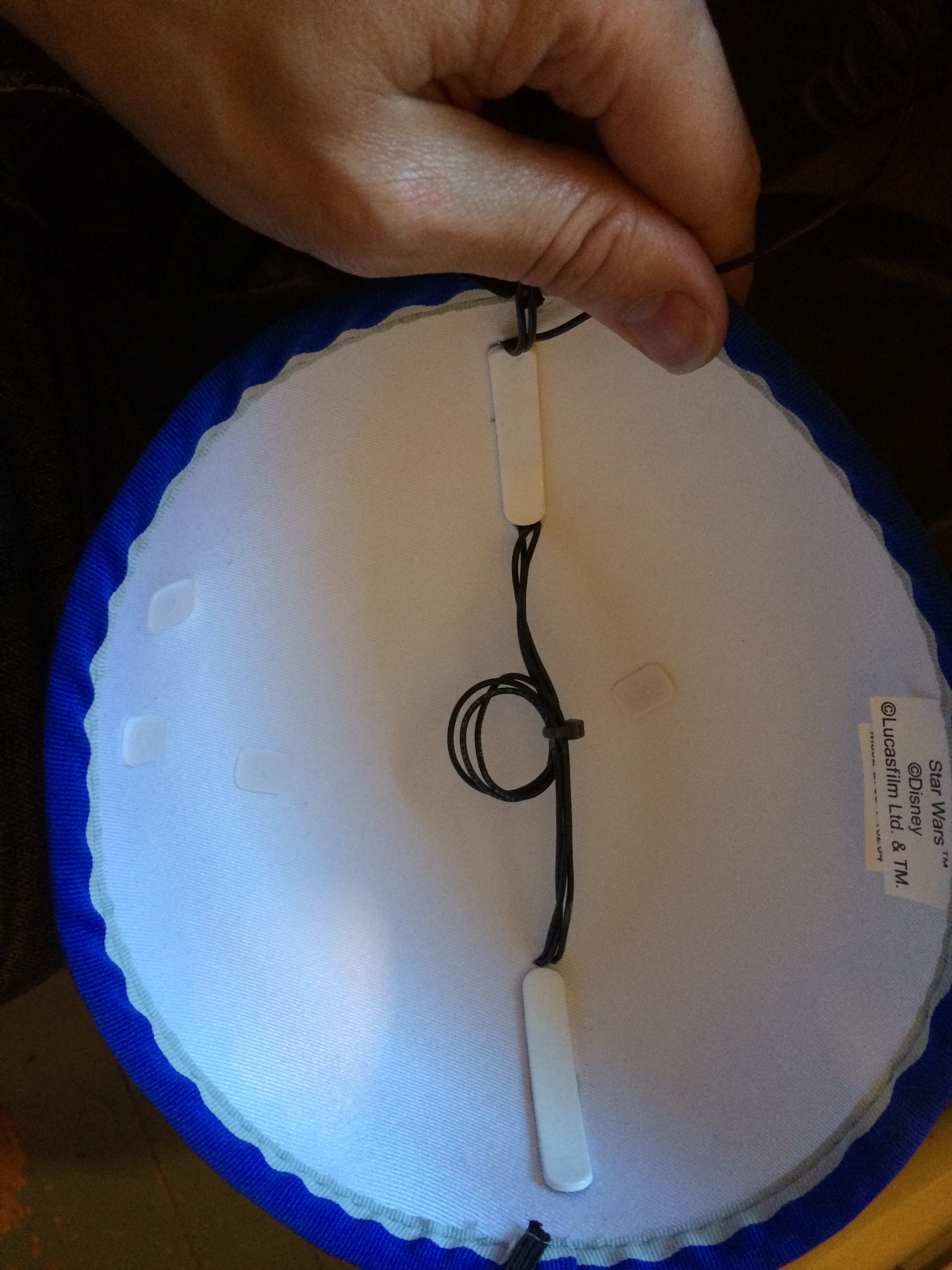
I then held the battery where the elastic harness would go: at the inside top center of the hat. The battery is the heaviest piece, so I didn’t want it throwing off the hat’s center of gravity. I used permanent marker to mark its spot, then sewed in elastic strips.
|
|
|
|
|
|

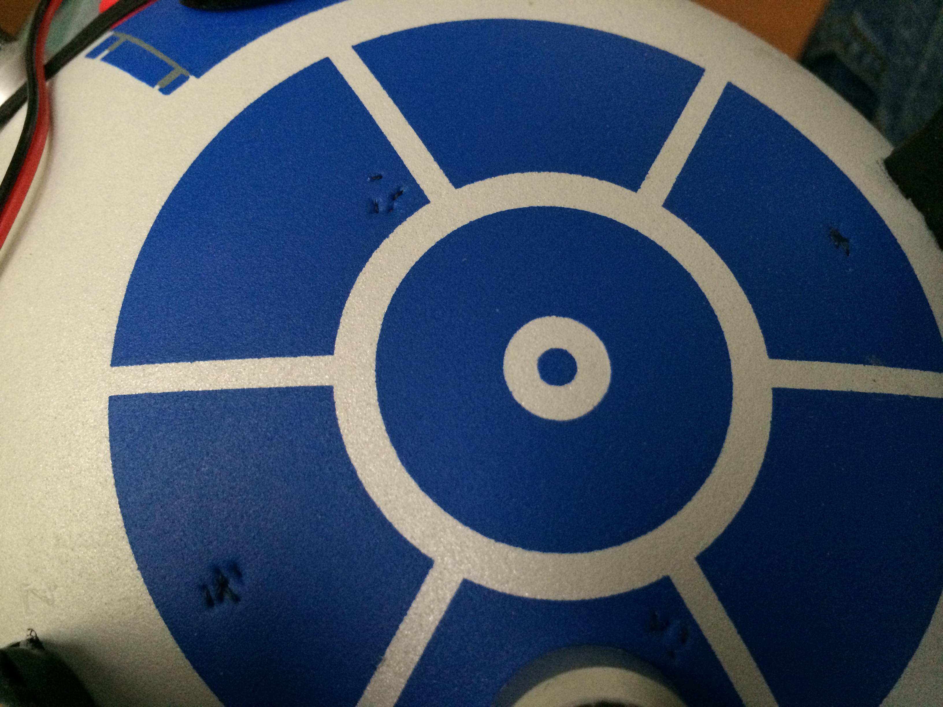
I then sewed down (gray thread this time) the leads between the first LED strip and the microcontroller, as well as the microcontroller itself. There was a spot on the outside graphics that looked perfect for the board.
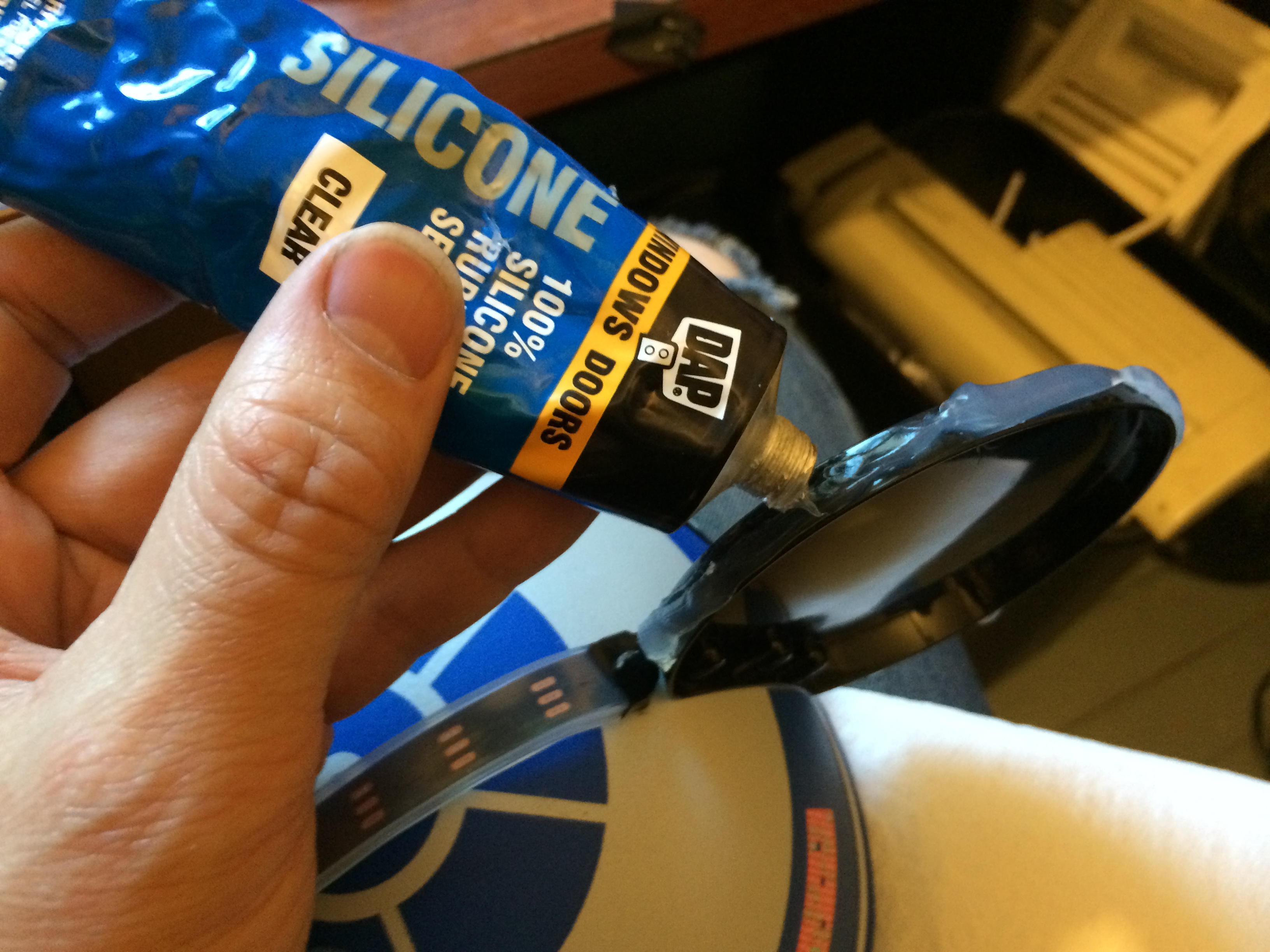
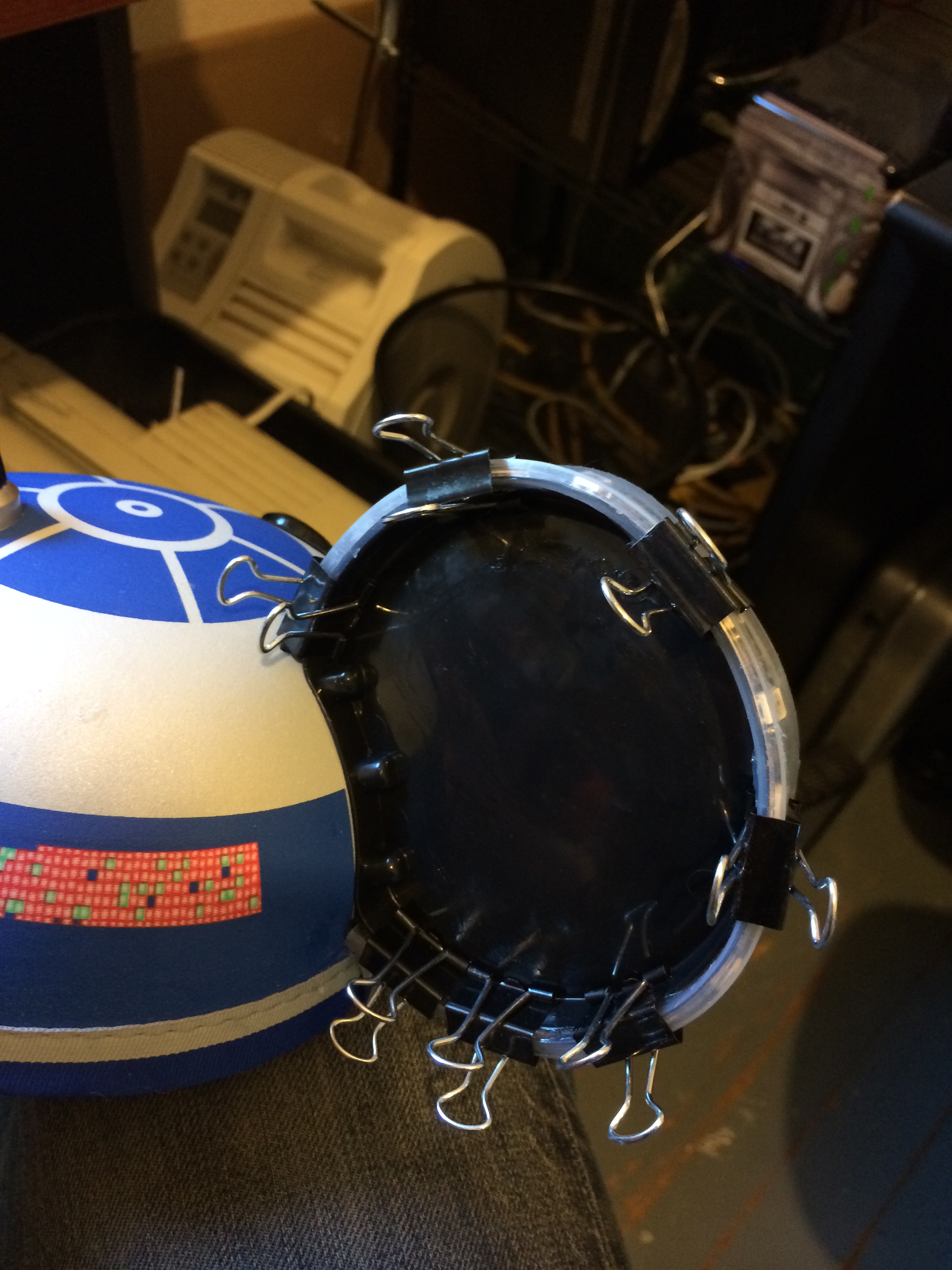
The next step was to glue down the LED strips. I used clear silicone sealant then temporarily held everything in place with binder clips.
Finally, I sewed down the excess slack wire
This design has no power switch. You just snake the power extension wire from the battery to the microcontroller and connect/disconnect as needed.
Programming is easy. The USB port is exposed. Plug in and upload. I started with the sample code for the Cyberpunk Spikes project, but tweaked it significantly to get those inward-spinning rainbow wheels.
One thought on “Building light-up R2D2 mouse ears (May the Fourth)”