This is Part 2 in a series of three describing the hardware behind the puzzle gadget I designed for Curtis’ birthday puzzle game. If you arrived at this page from elsewhere, you may want to start at Part 1.
The story so far: a secret surprise puzzle game, a gadget that had to “contain” a piece of paper upon opening, the decision to make that gadget electronic with screen and keypad and to make that paper printed on demand by a thermal printer. Would it work???
Fortunately, I had almost all the parts on hand. I keep around a couple of extra scratch Arduinos. You never know when a project idea will strike and it is great to be able to jump on it and start prototyping. I also had some OLED screens and matrix keypads around for some other projects I had not yet gotten to. The only thing I was missing was the thermal printer. Ordered!
The thermal printer arrived the following weekend. As a proof-of-concept, before investing too much time and money into the project, I threw together a simple circuit and simple piece of test code. I knew that each part worked well on its own. On paper, I knew there were (just barely) enough pins for all parts to be connected to the Arduino. I wasn’t sure if all the parts libraries played well with each other and whether they’d like the particular pins I remapped them onto.
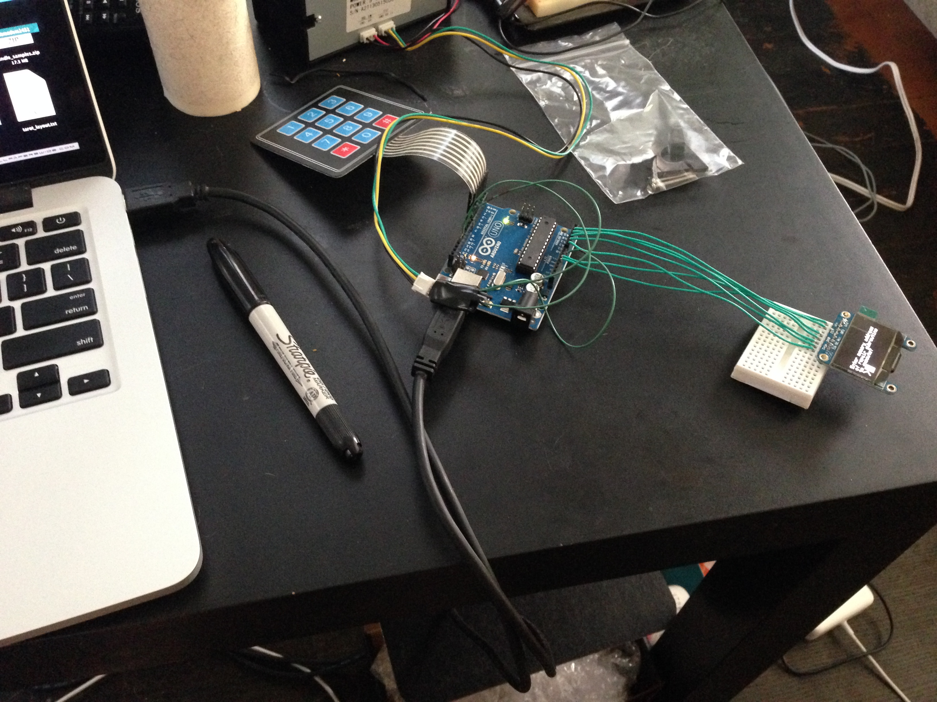
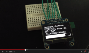
In this prototype, the screen prompts for a code and, based on the code, could print something out or display an error. I had answers for 42, 411, 911, and 867–5309. It worked beautifully. I shared the following video with the rest of the team:
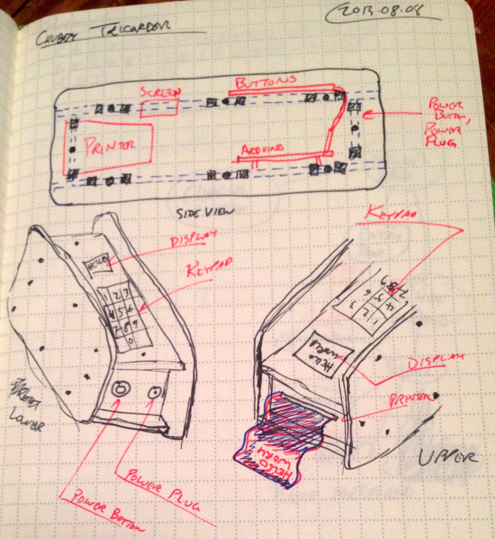
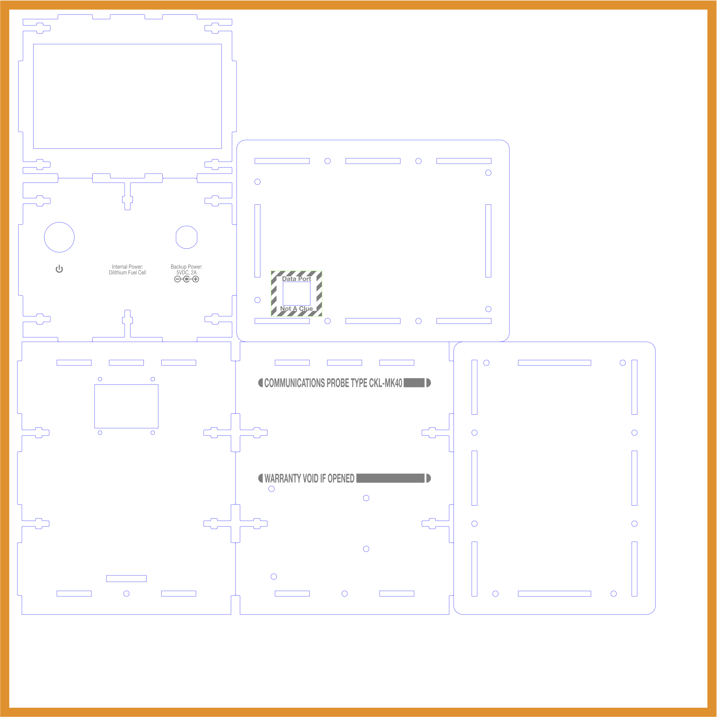
That confirmed the pieces worked together in harmony. The rest was code and presentation. Next up was the enclosure. I knew I wanted it black acrylic. The size was a series of trade-offs. My ultimate desire was to make it handheld. That was at odds with the size of the thermal printer and the behind-panel depth of the power button I wanted to use. I also wanted enough space inside so that I could get to the parts without feeling like I was working on a ship in a bottle. It took a few rough sketches to get a general placement that felt right, with regard to both the internal volume and the external placement. The printer had to be “up top” so it printed right-side up. Although I mulled over swapping their positions, I decided the screen had to be above the keypad. The power jack and button had to be somewhere and I wanted the Arduino’s USB port exposed for ease of programming.
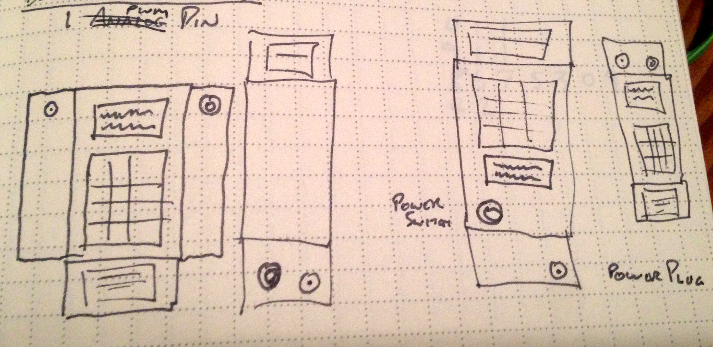
I finally settled on one particular arrangement. This sketch isn’t to scale — the overhanging edges are exaggerated — but it conveyed a rough idea of how both the internal and external pieces fit together.
With this in mind, I set forth to design the enclosure. But first: where would I build it? For me, location dictates materials and measurements. My choices were ADX or Ponoko. ADX is local, but they don’t have a materials library. I can get acrylic a few blocks away from TAP Plastics, but TAP only sells acrylic with fractions-of-inch thicknesses. I could get 1/8″, but the shape library I’ve built up over the years is primarily 3mm, which is close, but not close enough. I couldn’t easily reuse a lot of my shapes. ADX also requires a bit more babysitting. I have to make an appointment, get the plastic, bring it in, and stand by as they go over my print files. It’s fun, but I can only make it to TAP on Saturdays and ADX on weekends. If I had model files on a Monday or Tuesday night, it would take a good chunk of my time on the following Saturday to get them cut. With Ponoko, I could upload the files immediately. Their online scanner can perform the sanity-checks that the ADX folks do by hand. You can pay a few more dollars to bump your job to the front of the queue, and because they’re on the left coast, shipping is fairly quick. I could upload the design on a Sunday or Monday and have the cut acrylic in hand on Friday, freeing up a big chunk of the weekend. On a longer timescale, I would have gone with ADX and used it to build up my 1/8” acrylic library of cuts, but I opted to pay a bit more for the convenience and speed of Ponoko to reduce the overall project risk.
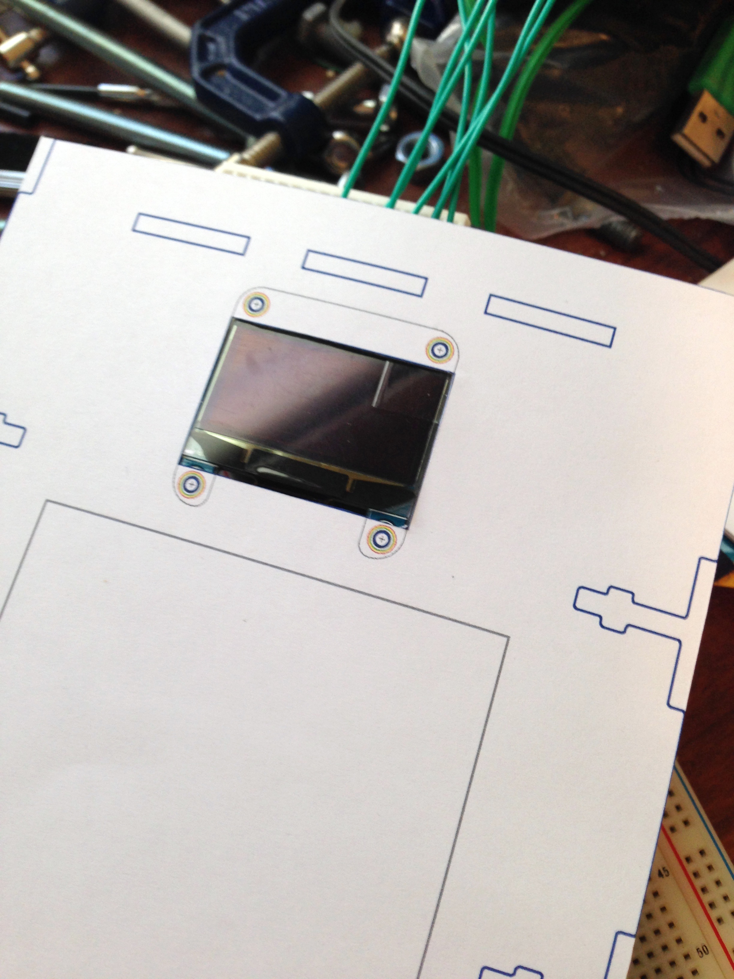
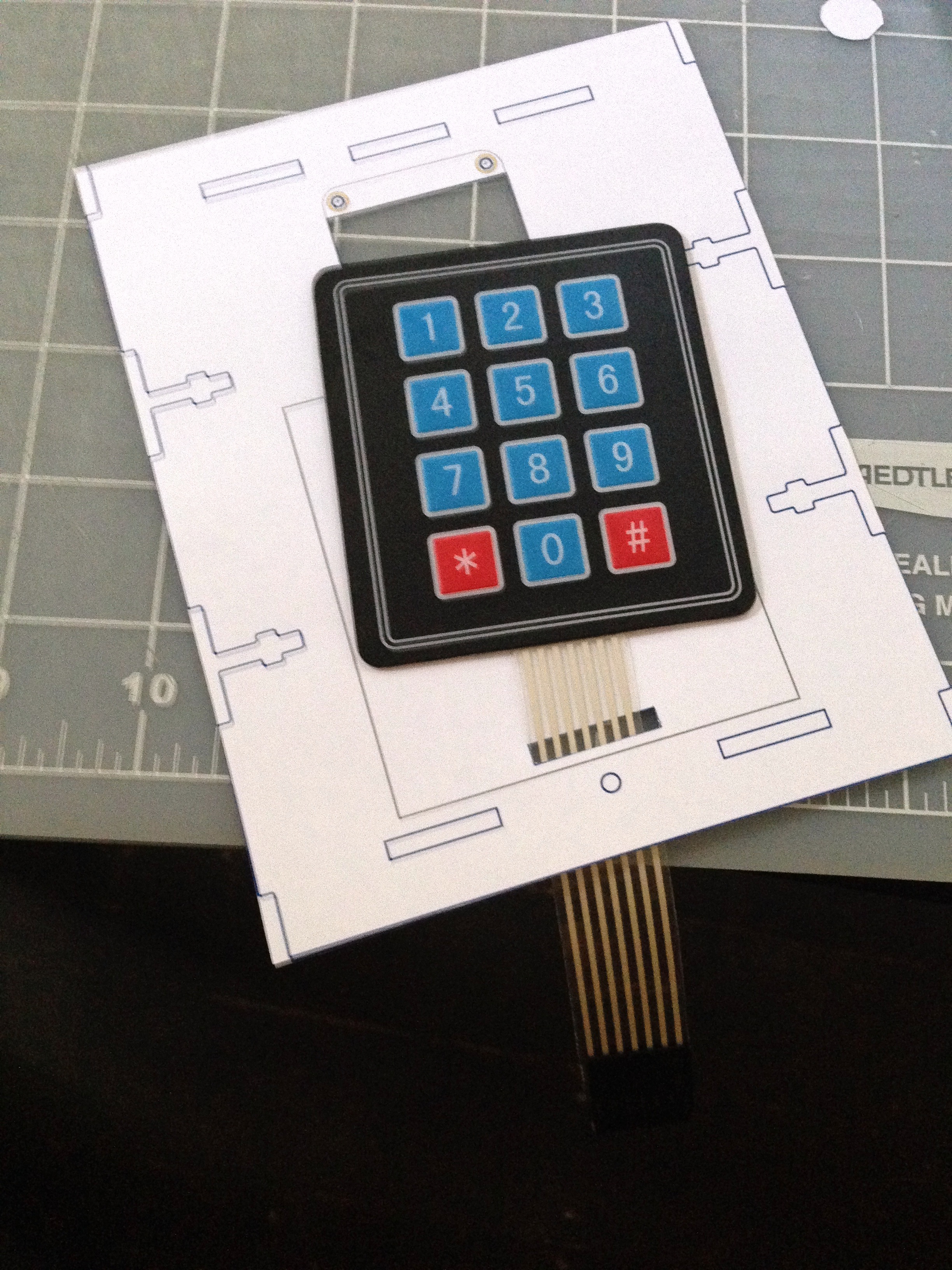
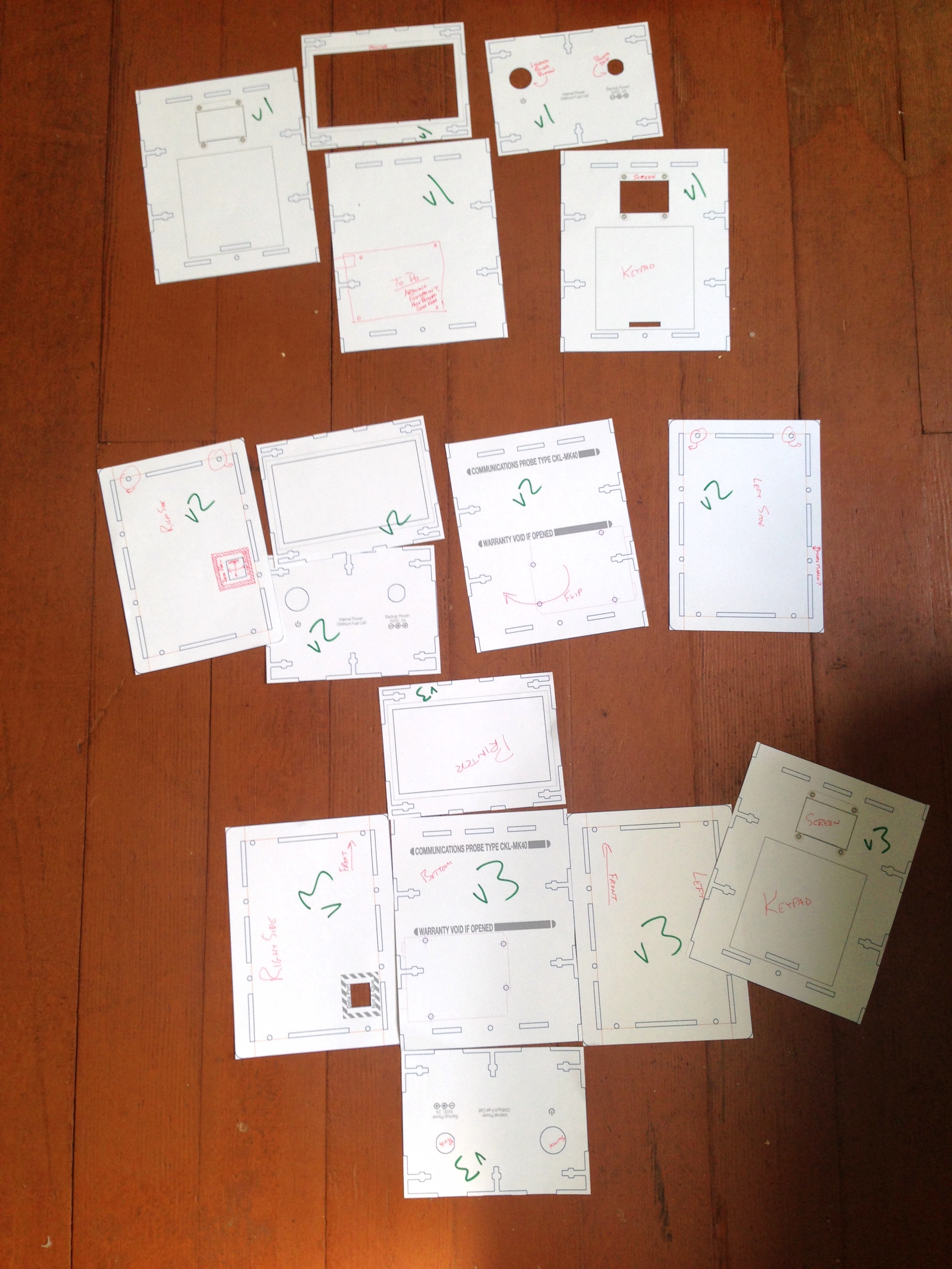
I started with an initial draft in paper of just four of the six sides. This was to get the initial parts correct as well as ensure the cutouts for screen, keypad, printer, button, and power jack were correct. A few X-Acto cuts later, I had verification. Revision B built up the sides and revision C corrected a few dumb copy/past errors with slot and tab alignment. I uploaded the files, paid the $29 (plus queue-jumping fee plus shipping), and got to wait a week.
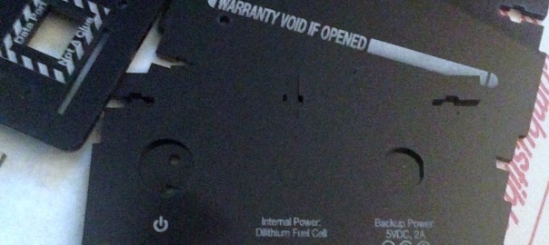
I focused back on the code for that week until the acrylic panels arrived. Consequently, I added a new component to the design, as well: a wireless communications module, but more on that in the next post. The panels arrived looking beautiful:
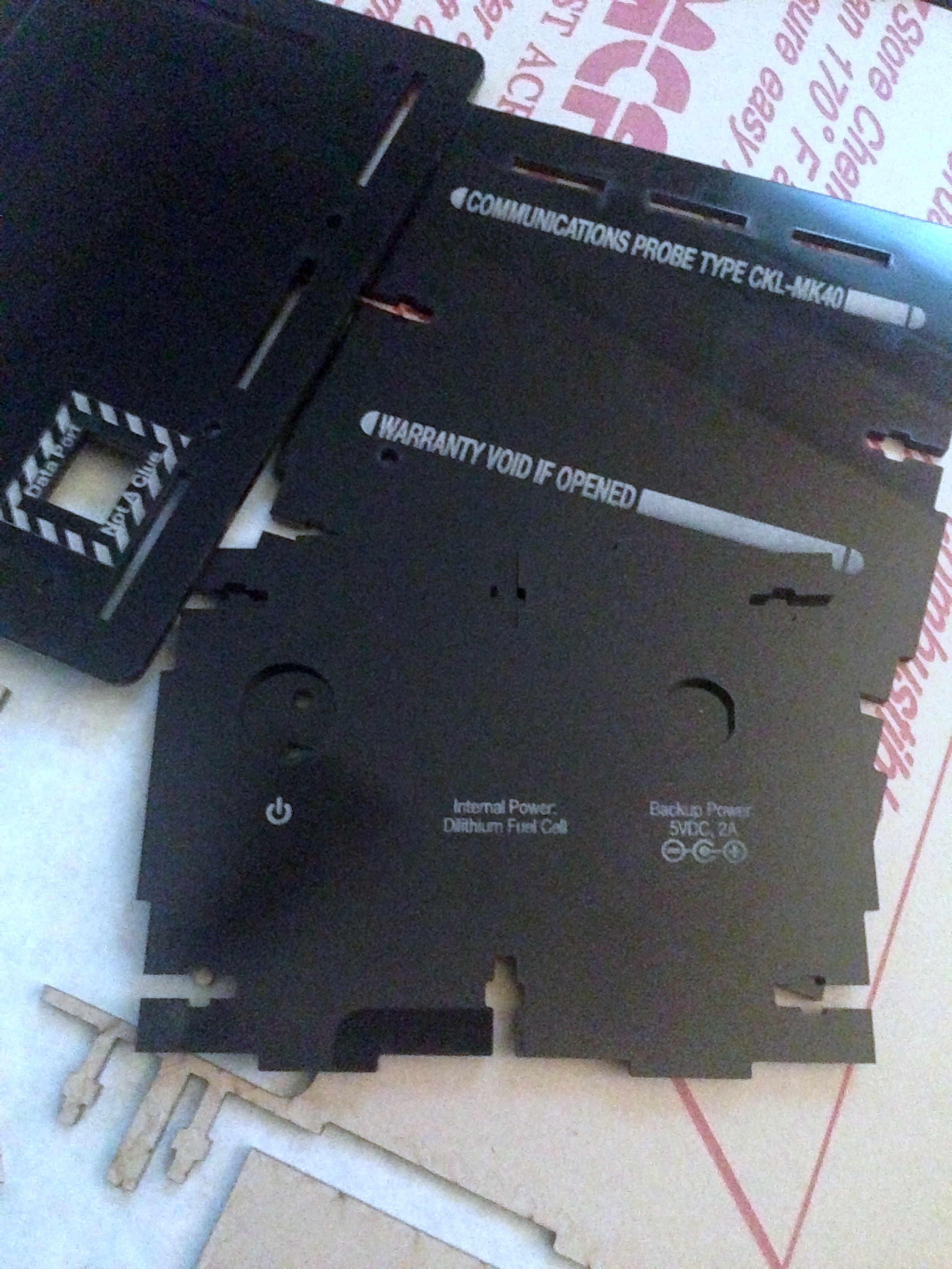
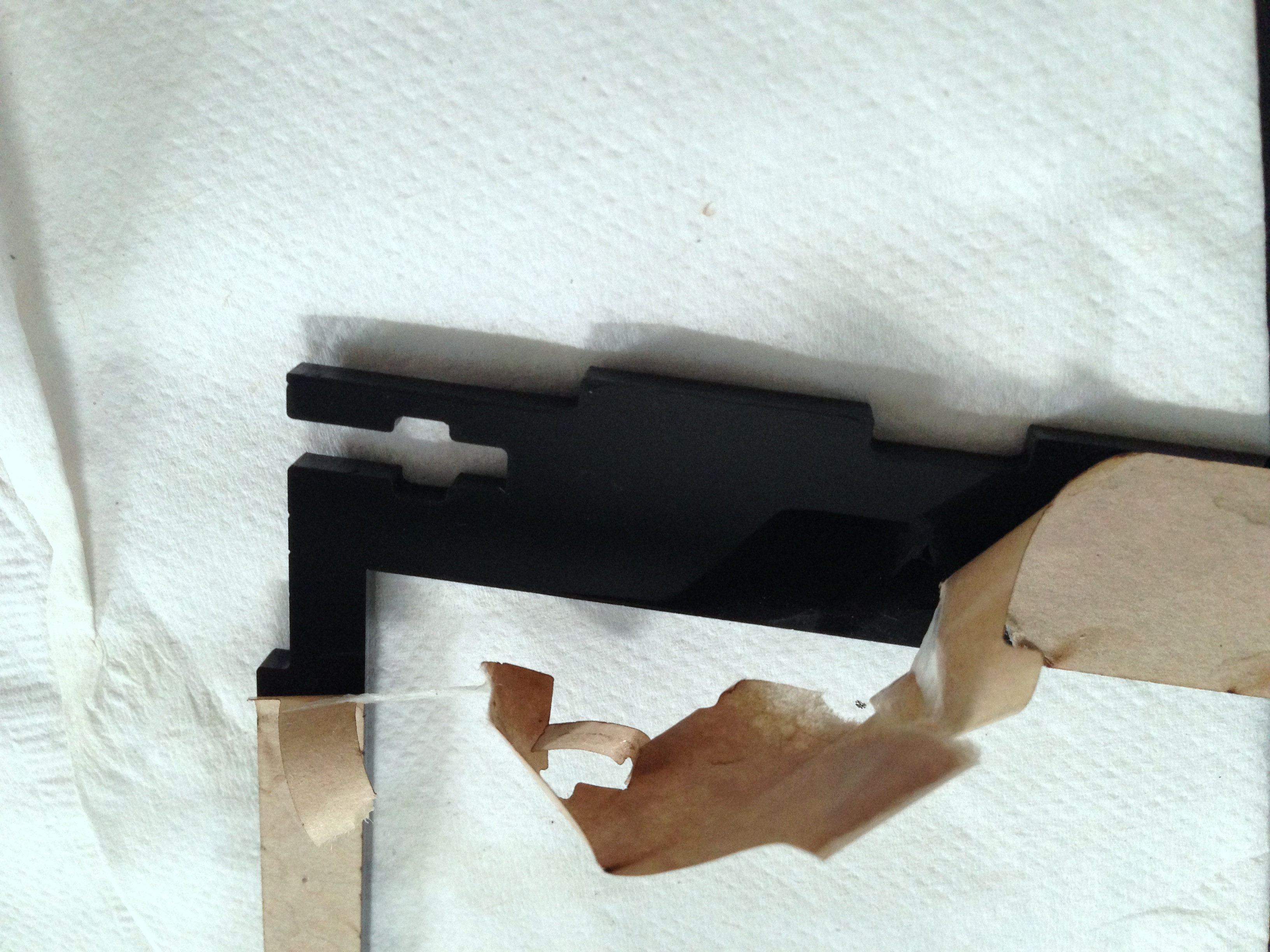
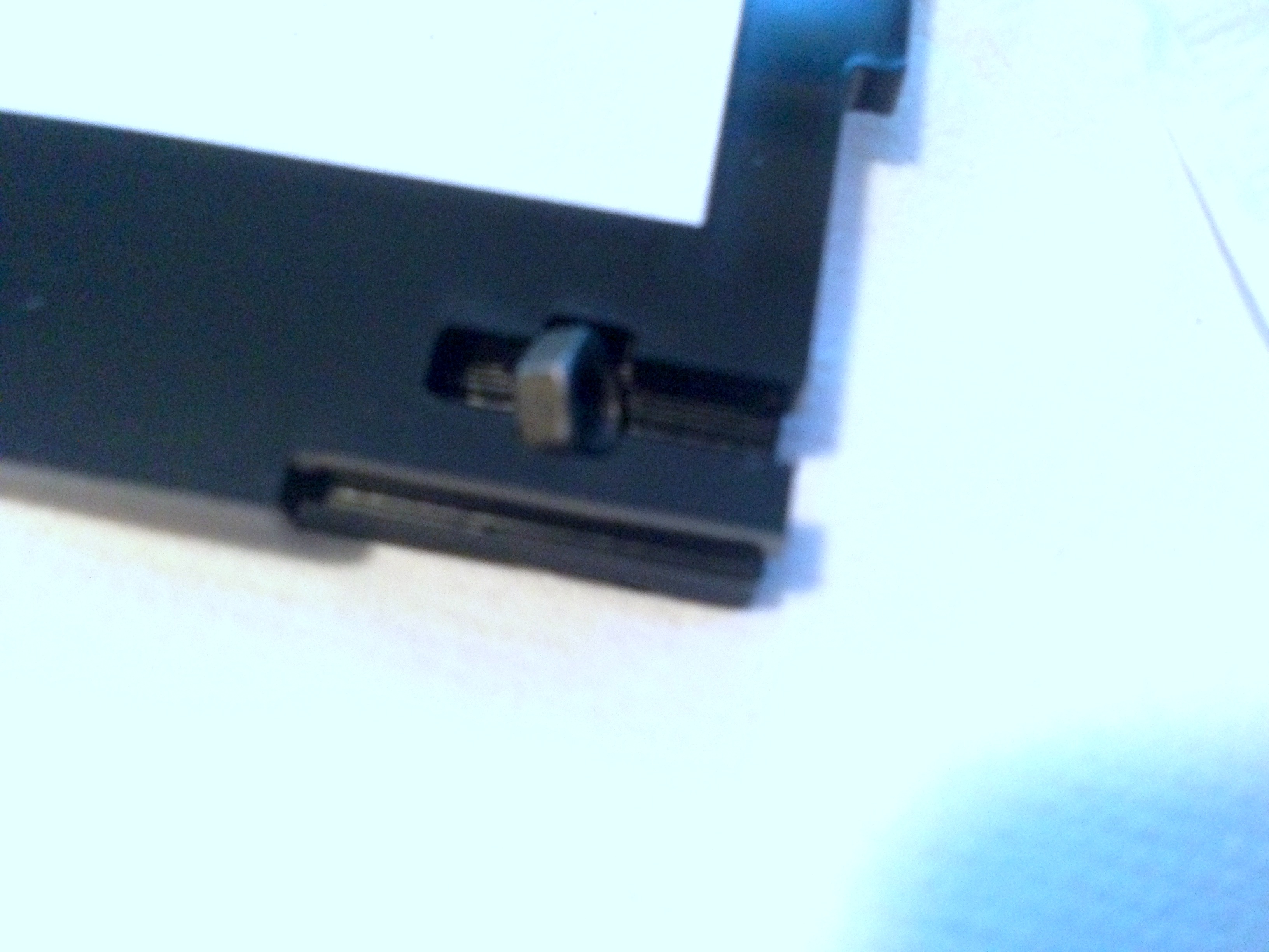
But they did have a problem. The previous laser project I worked on was in wood, which has different strengths than acrylic. I’d forgotten that I really hadn’t left much space on the printer edge for each of the four the bolt-retaining slots. In fact, they were so thin that one of them broke when I peeled off the protective adhesive paper.

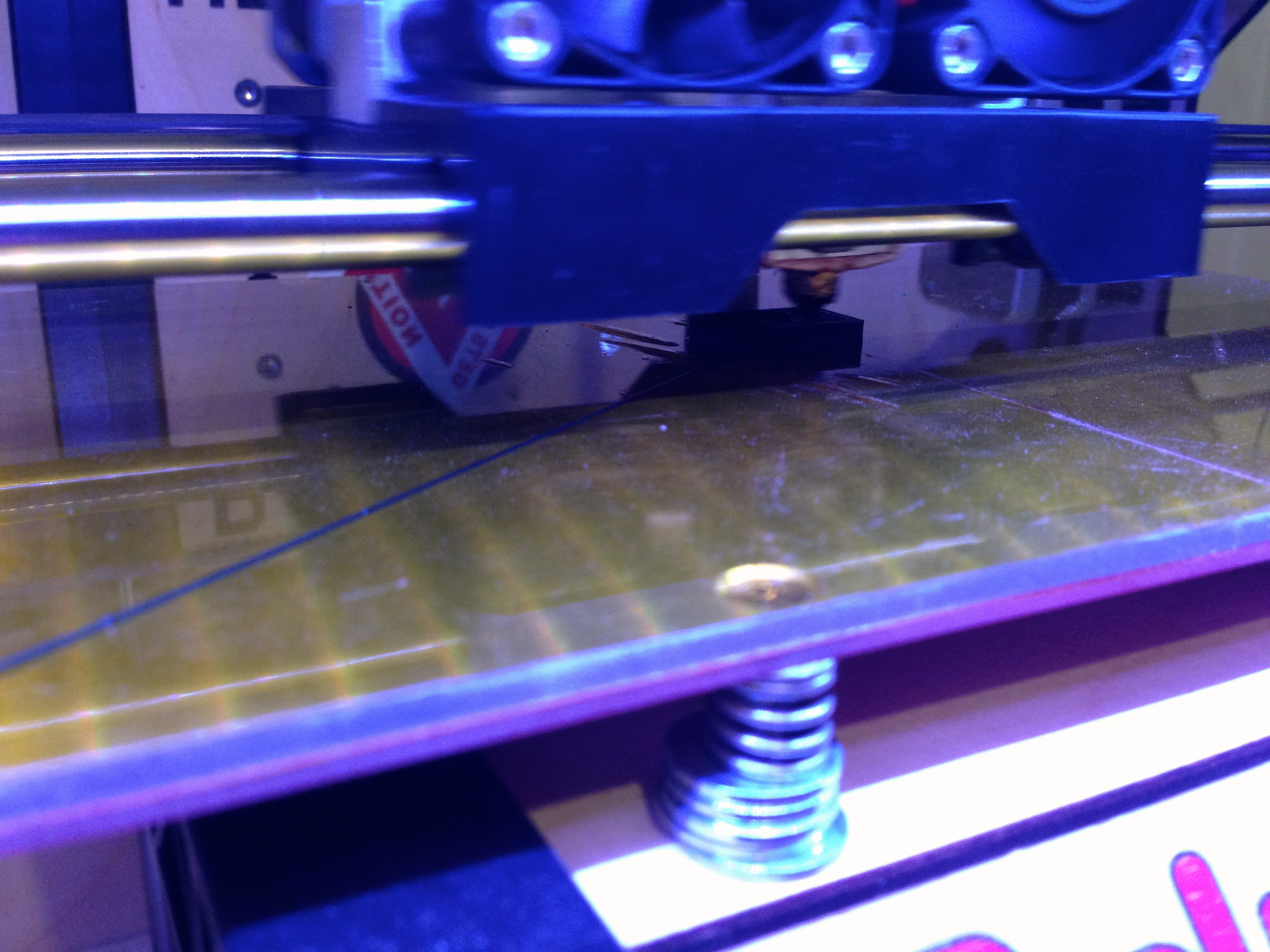
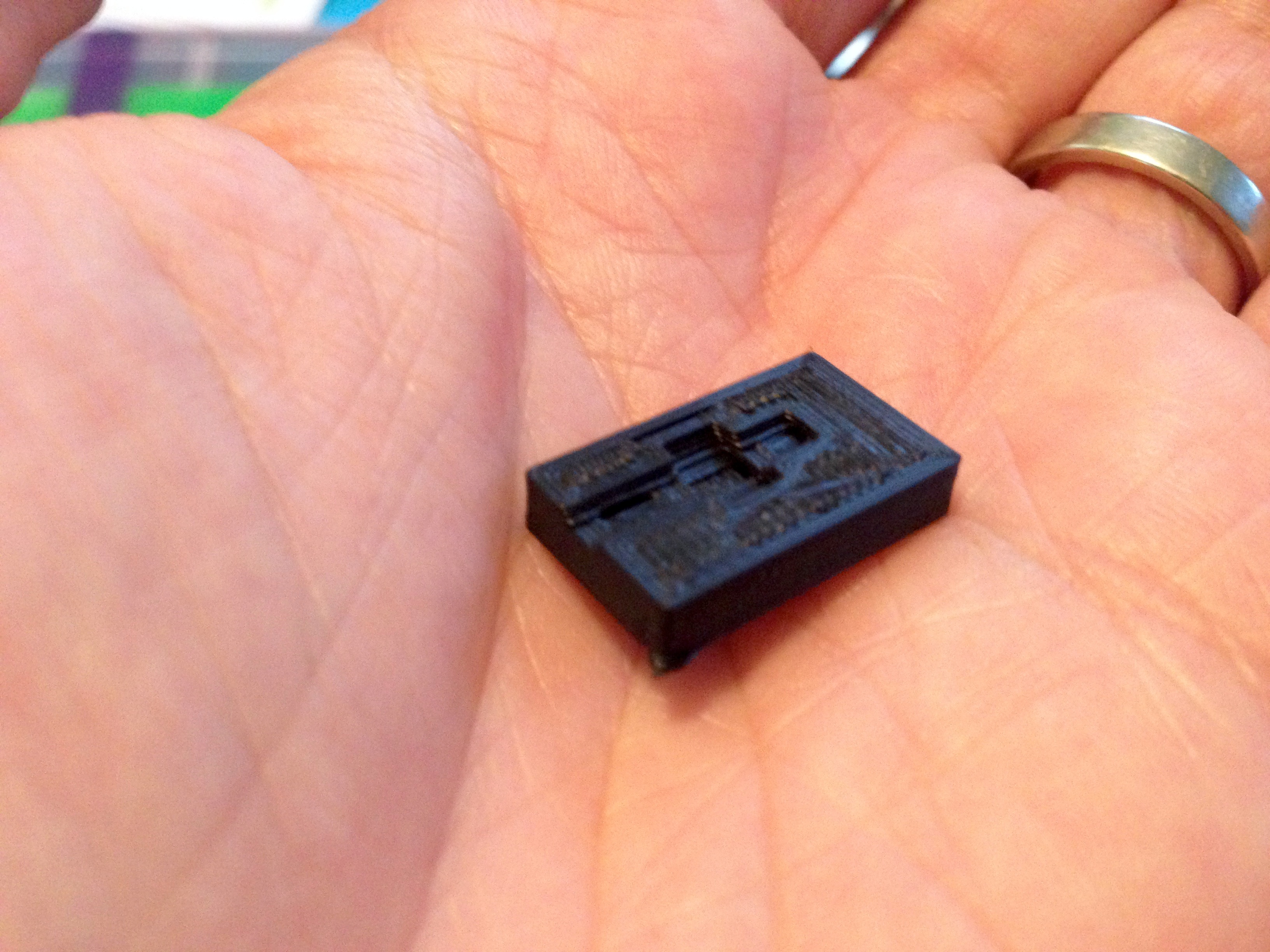
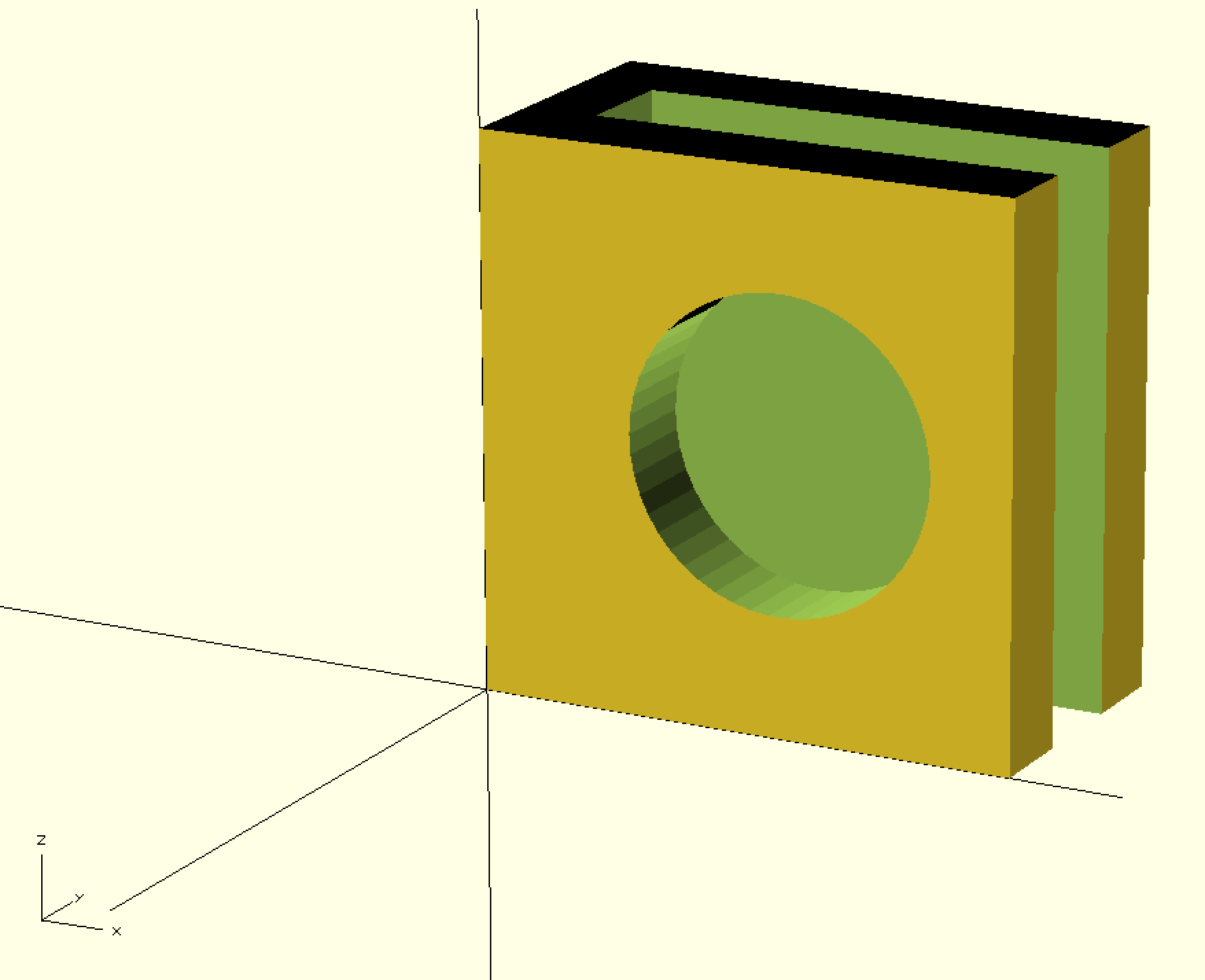
No problem, actually. When all you have is a hammer, everything looks like a nail – but when what you have is a 3D printer, everything looks like a shim or a bracket or some other similar problem waiting to be solved. I used OpenSCAD to design the following bracket (and the three other ways to mirror it in the X and Y directions):
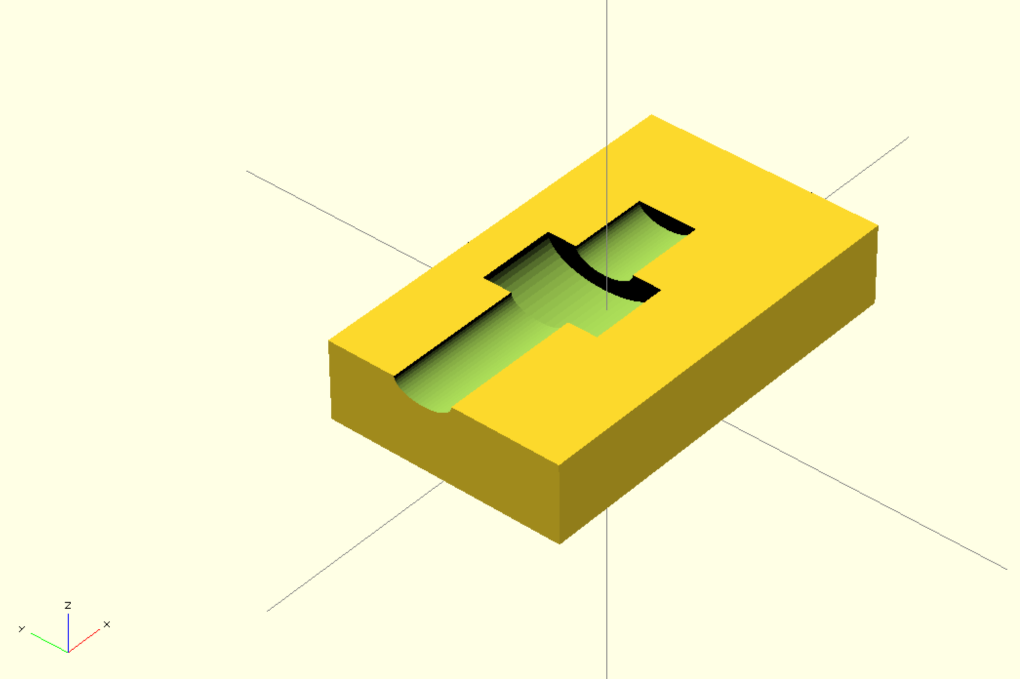
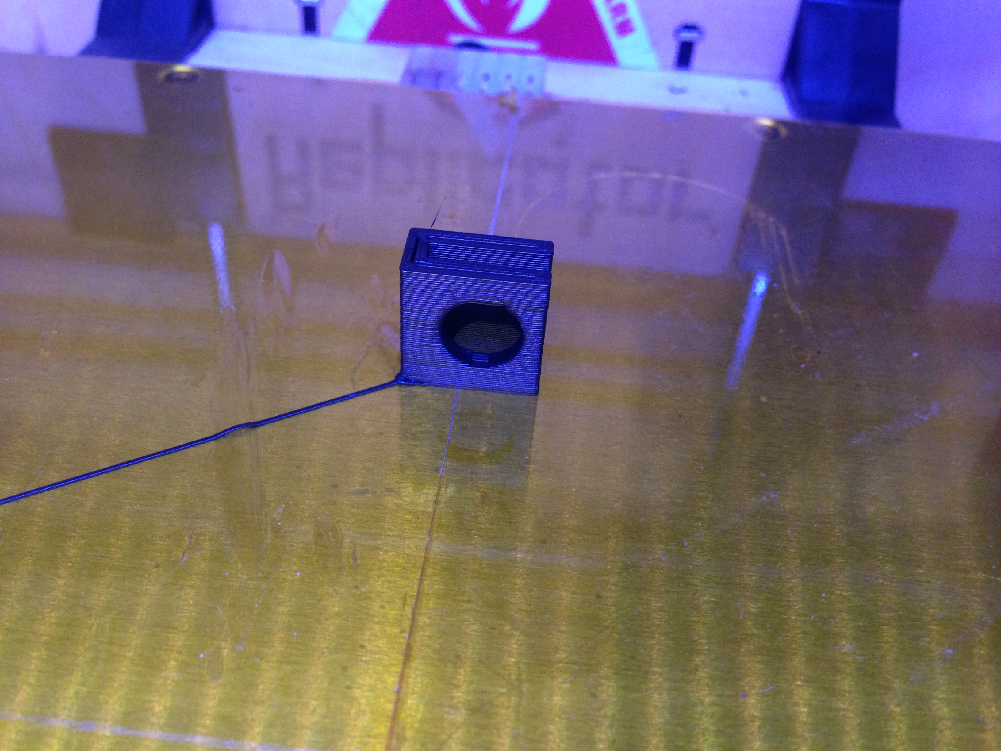
Printing was a piece of cake.
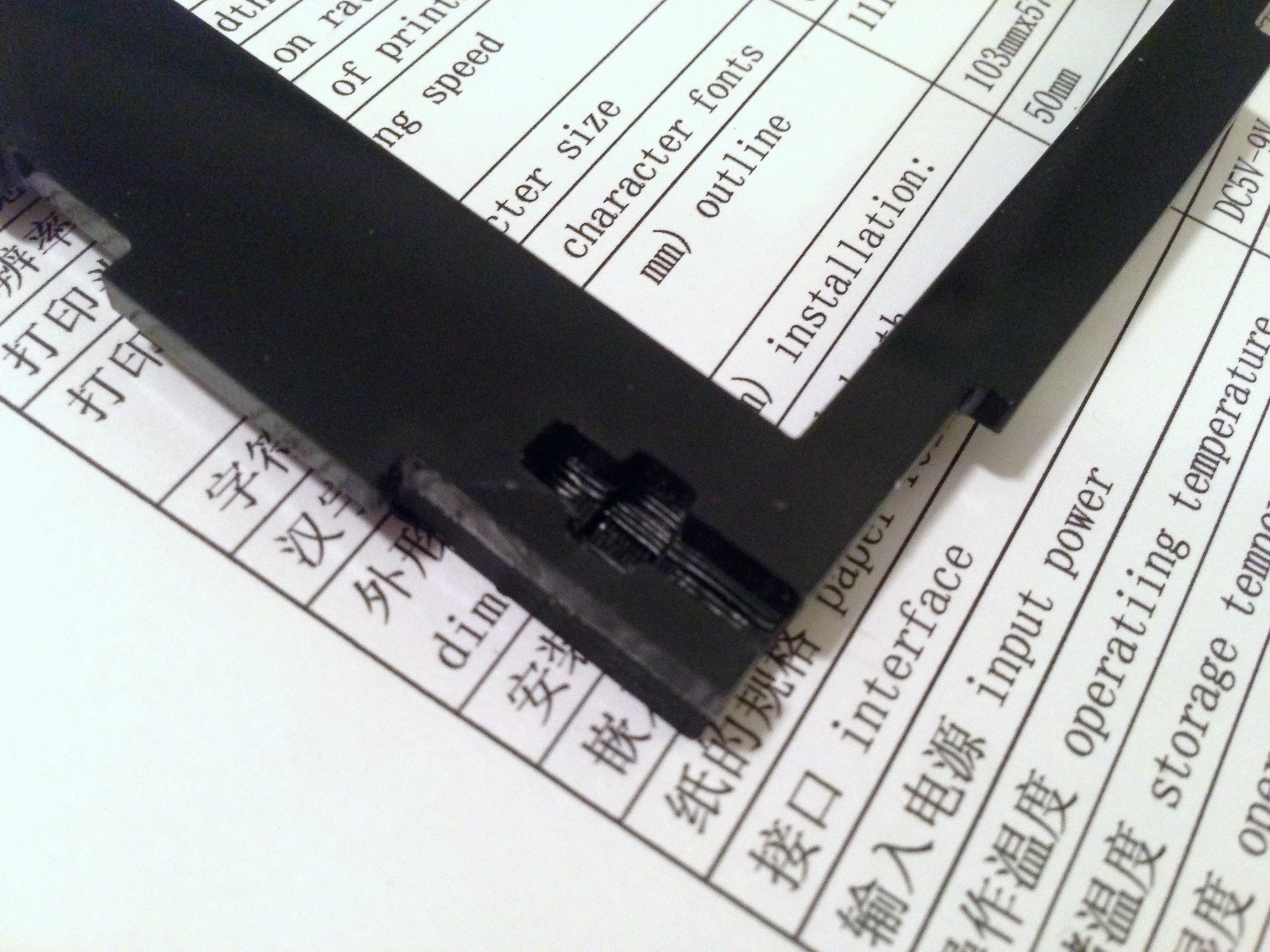
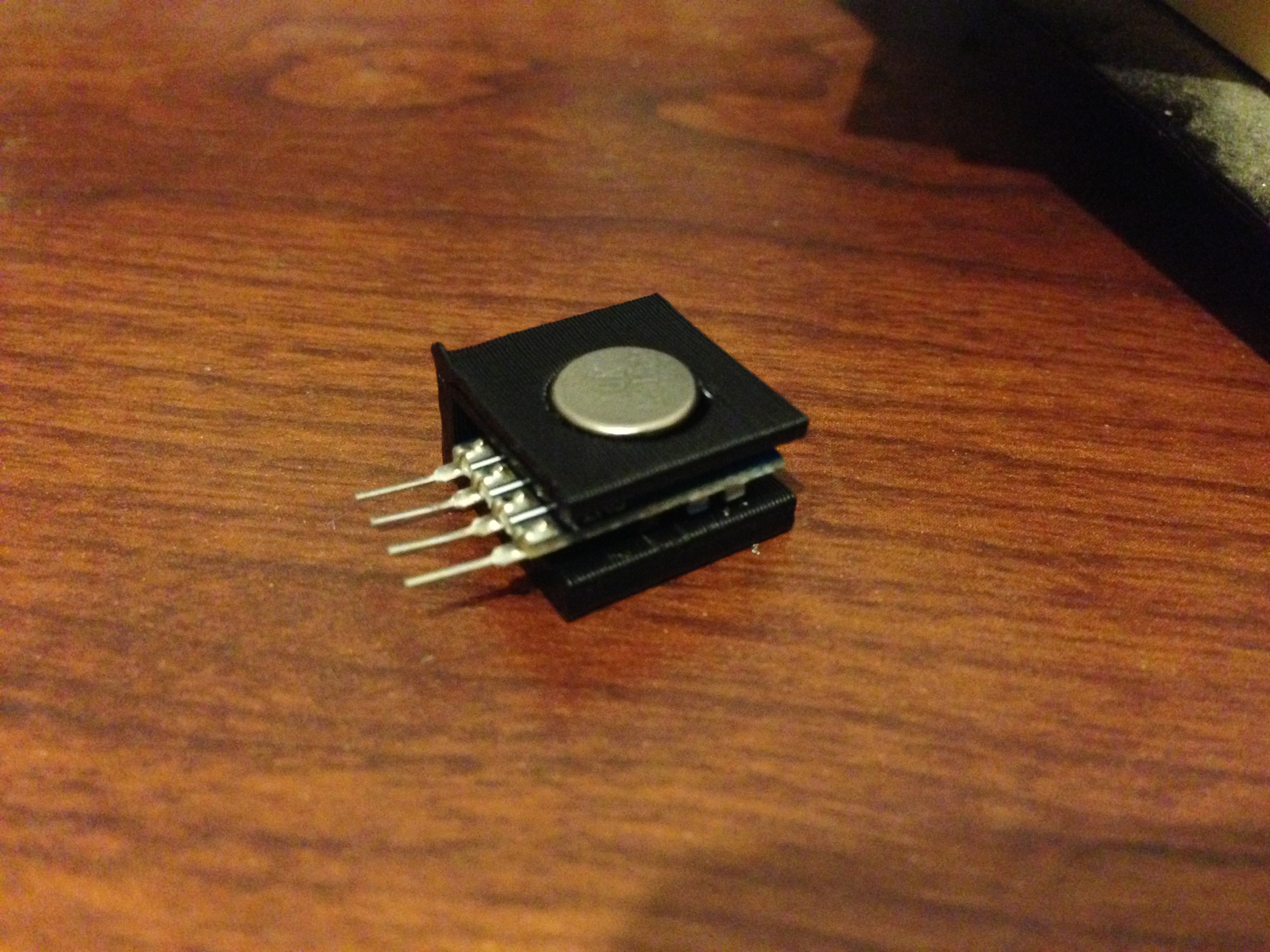
A quick depth measurement, add some superglue and all was well. Note: when gluing things to acrylic, you’ll want to sandpaper the surface a bit. It gives the adhesive a bit more to stick to.
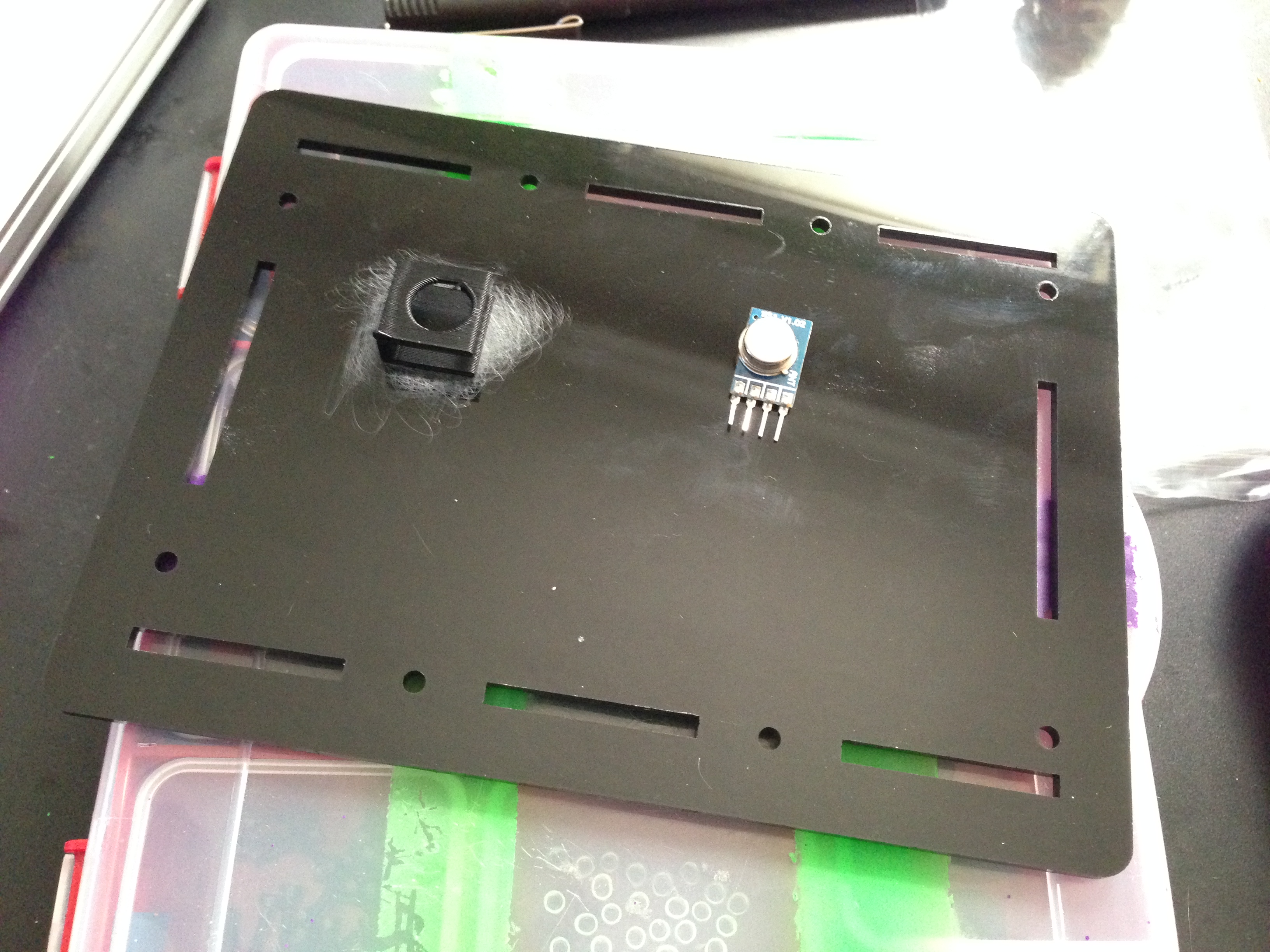
And while we’re talking about brackets and adhesive: I also designed and printed a bracket for the wireless module. All of the other components in the system were discrete parts that get fitted into holes in the case. They are then wired into header blocks that plug into the Arduino’s board. The wireless module was the outlier. I did not have a custom circuit board to mount it into and I did not want it rattling around inside the case. I designed, printed, and attached a bracket to the inside of one of the case’s panels that lets you clip in the wireless module.
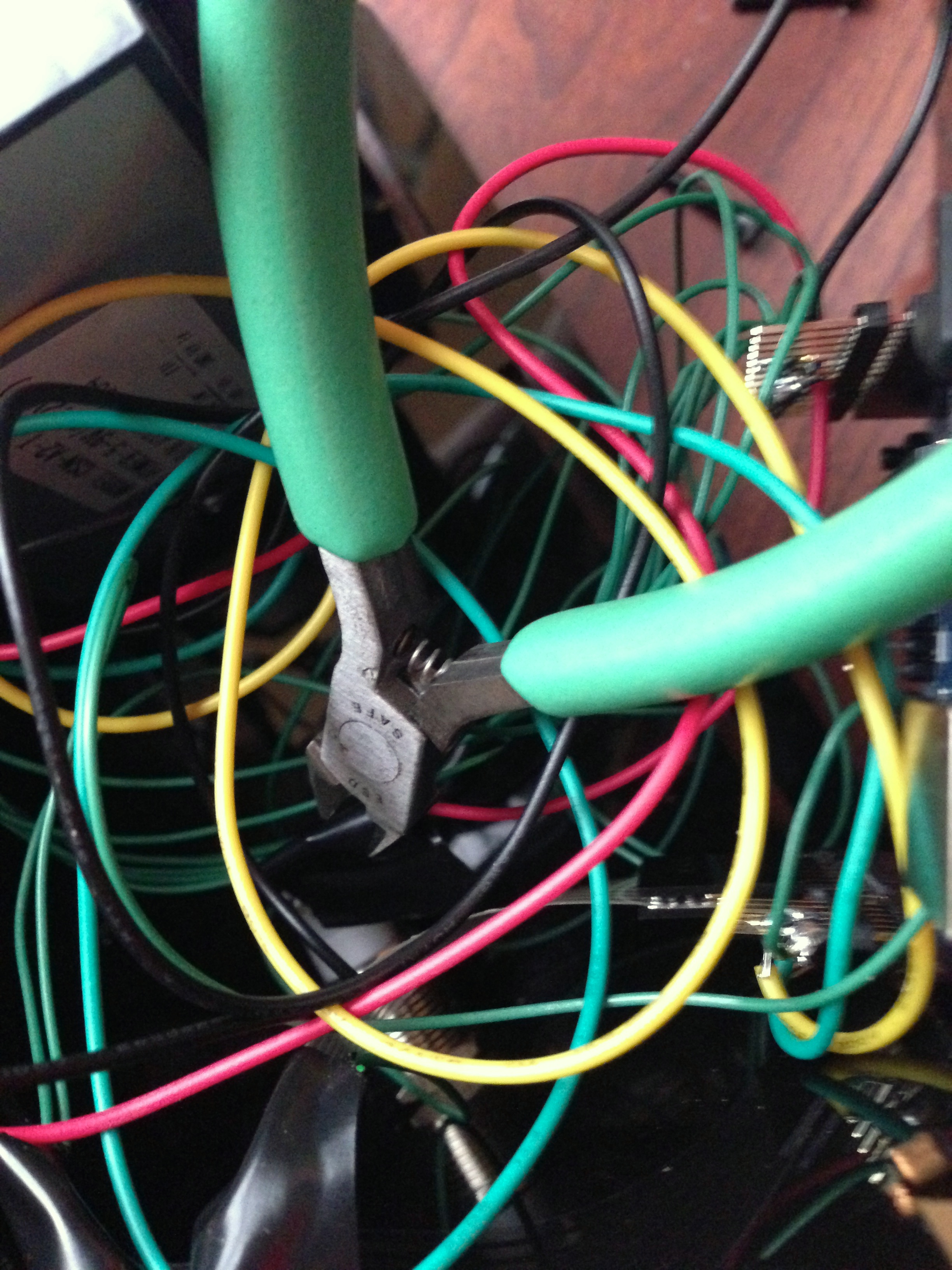
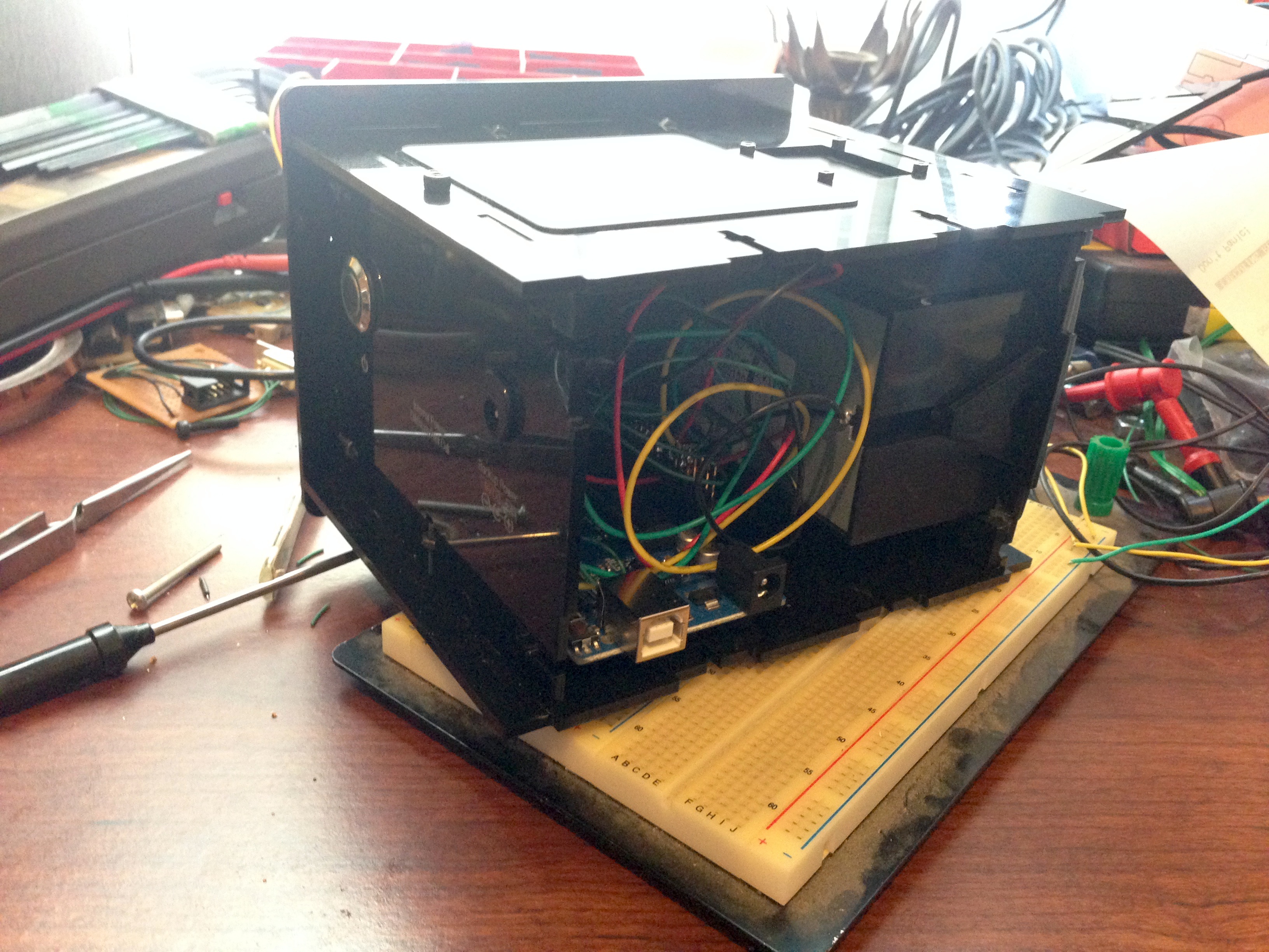
Everything looked good. At least on the outside. The inside was functional, but a rats nest of wires. “Quick! Cut the green wire!” “Yeah, but which green wire?!”
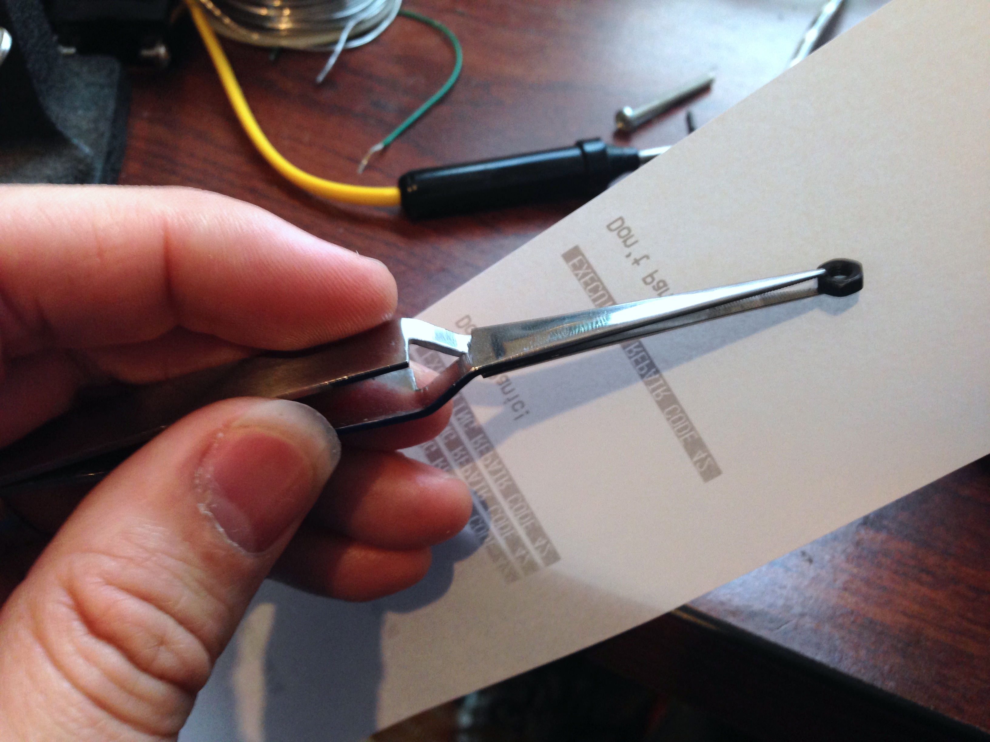
It was time to button up the case. If you’re building this kind of case, it is highly advisable to have some reverse-tweezers to hold things for you. Don’t drop the last nut inside the case!
But how well did it work? Proceed to Part 3!
One thought on “Designing the Chubby Tricorder”