I thought I would follow up the previous cat toy post with another one. I’m not obsessed with cat toys! Really! They just make good geometric models. The main content of this post will soon go into an Instructables page as an entry to win a 3D printer in the Make It Real Challenge, but I wanted to start with a copy here on my own blog.

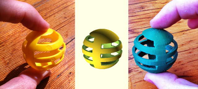
There are some cat toys at the house that are particularly popular with the local residents. They are simple hollow spheres with cut-out slots. They are great for kitties to kick around — small and light. After staring at one for a few minutes, piecing out the geometry, I realized that this would make a great instructional design for an introduction to 3D CAD modeling using simple geometric shapes and boolean transforms.
Before we begin, you will need two things:
- A copy of OpenSCAD. This is “free” in every sense of the word — it costs nothing AND is an Open Source project that people from around the globe contribute to and use. You can get it for Mac, Windows, or Linux.
- A web browser tab open to the OpenSCAD User Manual. OpenSCAD works like a programming language and although I’ll step you through the process, it is always good to have a language reference handy.
If you look at the original cat toy, it is a ball. That is to say, it is a hollow sphere (or spherical shell if you want to get fancy). That ball then has slots cut away at regular intervals. I did a little bit of measuring beforehand.

Let’s start by making the sphere. This is a simple one line “program.” There is an extra line up top that you can modify to produce different detail levels. I find that a value of 30 is good to do most work in, though I bump that up to about 100 when I am ready to produce a final render. This sphere has a radius of 20mm. Remember that the radius (20mm) is half of the diameter (40mm).
DETAIL = 30;

sphere(r = 20, $fn = DETAIL);
Type this code into the text area on the left of the OpenSCAD window. Go to the “Design” pulldown menu and select “Compile.” In a few moments, you should see a sphere in the right half of the OpenSCAD window. You can click and drag with your mouse to rotate the 3D shape and use the mouse wheel to zoom in and out.

If we were to print this sphere on a 3D printer, it would be solid. We don’t want a solid ball, but a hollow shell. Let’s subtract enough away to give us a 2mm shell. We do this with the difference() function. This function takes a list of two or more objects, draws the first one, and then subtracts each of the other ones. In this case, we will make a slightly smaller sphere inside and subtract it.
DETAIL = 30;

difference()
{
    sphere(r = 20, $fn = DETAIL);
    sphere(r = 18, $fn = DETAIL);
}
Now, select “Compile” or use its hotkey (F5). Note that on my keyboard (a Mac), the F5 key is actually keyboard brightness and I have to use the “Fn” key to use it as an F5.
In the graphic window you will see…. something that looks exactly like what you had before. Except it is hollow now. How do you know? Let’s take a quick bite out of it with a cube.
DETAIL = 30;

difference()
{
    sphere(r = 20, $fn = DETAIL);
    sphere(r = 18, $fn = DETAIL);
    cube(size = [20, 20, 20]); // temporarily use this to peek at the thickness
}
This program starts with the big sphere, subtracts out the smaller one, then subtracts out a cube. You may have to use your mouse to rotate around, but it should look something like this:

Now remove that cube line. We will do something very much like that to cut out the slots, except instead of cubes, we will use cuboids, which are the rectangles of cubes. Let’s just start with one to see how to line things up. We’ll do this:
DETAIL = 30;

difference()
{
    sphere(r = 20, $fn = DETAIL);
    sphere(r = 18, $fn = DETAIL);
    cube(size=[80, 40, 5]);
}
You’ll end up with a sphere with a slit similar to a Cylon eye strip. What’s going on here? Shouldn’t that have cut out a rectangle? It did, but the rectangle was placed directly on the origin. If you select “View -> Thrown Together” from the pulldown menus, then “Design -> Compile” you’ll see the combination of shapes. This is an extremely useful view of your virtual world when you are trying to subtract shapes and don’t understand what is going on.


We want it to completely intersect from one edge of the sphere to the other. To do that, we’ll need to slide it over a bit. We can do that with the translate() function, which takes the object following it and shifts it around on the x, y, and z axis. Let’s try it.
DETAIL = 30;

difference()
{
    sphere(r = 20, $fn = DETAIL);
    sphere(r = 18, $fn = DETAIL);
    translate(v = [-40, 0, 0])
        cube(size=[80, 40, 5]);
}


That’s the strip we’re looking for, but it needs to be offset just a bit from the center to give us that central support column. Let’s tweak that y value over a little bit more.
DETAIL = 30;

difference()
{
    sphere(r = 20, $fn = DETAIL);
    sphere(r = 18, $fn = DETAIL);
    translate(v = [-40, 4, 0])
        cube(size=[80, 40, 5]);
}

That’s great! Now we just need to add a few more! I’m going to adjust the height from 5mm to 4.45mm to get them to divide a little more evenly across the sphere. Let’s add some more translated cubes. It takes a little bit of math to get the positioning right, but you can add one at a time, experiment with positioning, and play with the results as you go.
DETAIL = 30;

difference()
{
    sphere(r = 20, $fn = DETAIL);
    sphere(r = 18, $fn = DETAIL);
    translate(v = [-40, 4, -20 + 2 * 4.45])
        cube(size=[80, 40, 4.45]);
    translate(v = [-40, 4, -20 + 4 * 4.45])
        cube(size=[80, 40, 4.45]);
    translate(v = [-40, 4, -20 + 6 * 4.45])
        cube(size=[80, 40, 4.45]);
}


Finally, the other half of cutouts goes in, offset from the first set. The code looks almost exactly like the first half:
DETAIL = 30;

difference()
{
    sphere(r = 20, $fn = DETAIL);
    sphere(r = 18, $fn = DETAIL);
    // right side
    translate(v = [-40, 4, -20 + 2 * 4.45])
        cube(size=[80, 40, 4.45]);
    translate(v = [-40, 4, -20 + 4 * 4.45])
        cube(size=[80, 40, 4.45]);
    translate(v = [-40, 4, -20 + 6 * 4.45])
        cube(size=[80, 40, 4.45]);

    // left side
    translate(v = [-40, -44, -20 + 1 * 4.45])
        cube(size=[80, 40, 4.45]);
    translate(v = [-40, -44, -20 + 3 * 4.45])
        cube(size=[80, 40, 4.45]);
    translate(v = [-40, -44, -20 + 5 * 4.45])
        cube(size=[80, 40, 4.45]);
    translate(v = [-40, -44, -20 + 7 * 4.45])
        cube(size=[80, 40, 4.45]);
}


Finally, you can crank up that DETAIL value when everything looks good. This will give you a higher quality 3D model with more surfaces, but it takes a little longer to generate. Go to “Design -> Compile and Render” on the pulldown menu for your final render. Assuming that looks good, go to “Design -> Export as STL” to save it as a 3D file. Most 3D printers and 3D printing services use this file format.
Congratulations! You created a cat toy using geometry! Time to print!
On a home 3D printer, even if you build using support structures, the upper slats will have gravity working against them. They’ll end up sagging a bit and kind of stringy on the bottom. You will get a ball that is structurally sound, but looks a little warped. If you have a small metal file or X-Acto knife, you can manually clean it up a little. Industrial printers typically do not suffer from this sort of problem because they use a different process for printing and support.
I have a zip file (cat_ball.zip) containing source for each of these steps. It also contains a mondo-mega final OpenSCAD file called a parametric model. This is a model where all of the important numbers are distilled and extracted to the top (much like DETAIL is in the above examples). This then lets you easily change the size of the ball, the wall thickness, the number of slots, and the width of the support structure (i.e. the depth of the cuts). You can then make all sorts of crazy variants just by changing a few numbers. You want one that is 50mm in diameter with a 5mm thick shell and 19 cutouts? There you go! But good luck printing this variant on a home 3D printer.

One thought on “From Atoms to Bits to Atoms: A Cat Toy’s Journey”